the12volt.com spacer
icon

2004 Saturn Ion Passlock II Bypass


Post ReplyPost New Topic
< Prev Topic Next Topic >
Krysolma 
Member - Posts: 14
Member spacespace
Joined: January 29, 2005
Posted: June 22, 2010 at 10:59 AM / IP Logged  

Hi,

I have a question about Passlock II on a 2004 Saturn ION.  These cars are nutorious for not starting in cold and humid weather due to the ignition switch.  Replacing the switch is a temporary fix as it will go bad again (it has twice now).  That is the reason I want to permenantly bypass it for good.   I have done this with 1% tolerance resistors on other gm cars in the past but they always had dedicated cylinder wires for this, where as in this car its part of the ignition switch wiring.

So here is my question.  This is the info I was able to gather on this car

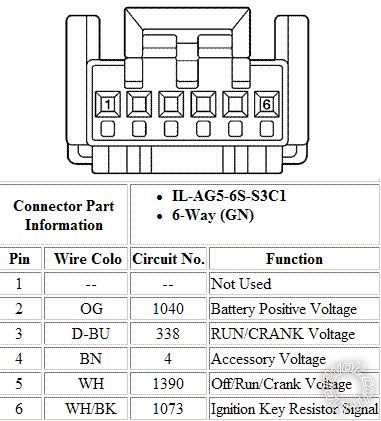
Ignition Connector Wiring

2004 Saturn Ion Passlock II Bypass -- posted image. 

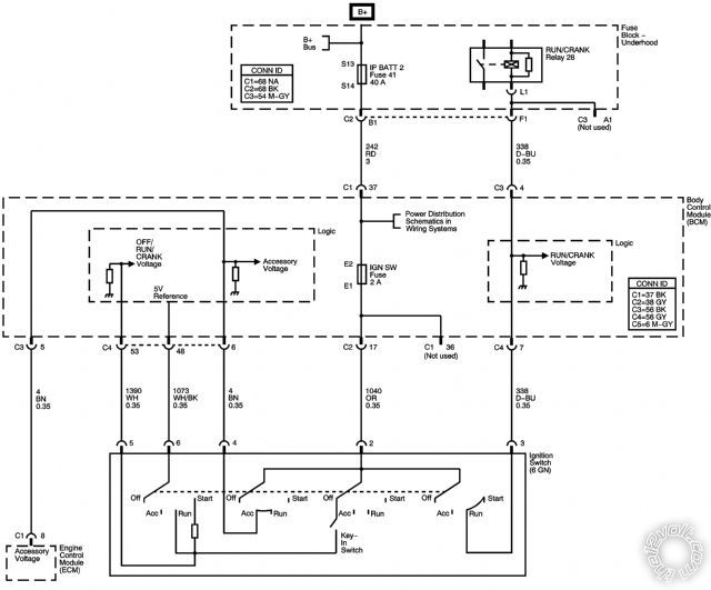
Ignition Swithc functional schematic

2004 Saturn Ion Passlock II Bypass -- posted image.

So from the look of those two thing, the white wire is 12 volts when the key is insteRED / accessory, then its at 5 volts while the car is running, and 5 volt thru resistor while starting/cranking.

Looking at some bypass installation pictures for this car, they have you cut the white wire and place the 555l in line.  So I am thinking that simply cutting the white and WHITE/ black wires and placing a resiston betweeen them going to the BCM would do the trick.  This would be almost the same thing that the 555l does, only while starting.  So can i simply put the resiston in-between the wires, or will the car freak out because it doenst see the 12 and 5 volt signals for accessory/run.

Please help me with this, I want to end these starting problems once and for all.  It is a huge nuisence and i dont care about my car being stolen.  I just want to be able to use my car when i want to use it. 

Also, I have read about just cutting the white wire while the car is running to put the bcm into a "system failed after start" mode but dont like the idea of having lights on my dash or cutting the leads to them.  I'm much rather take care of it properly. 

tedmond 
Gold - Posts: 4,610
Gold spaceThis member has been recognized as an authority in Mobile Security and Convenience. Click here for more info.spacespace
Joined: January 06, 2007
Location: Ontario, Canada
Posted: June 22, 2010 at 12:31 PM / IP Logged  

its against forum rules to show how to disable an antitheft system.

but if you go to downloads and search PASSLOCK.

you can use that diagram, just no need for the relay, just get the right resistance.

ps, i didnt show you lol the instructions will 2004 Saturn Ion Passlock II Bypass -- posted image.

Ted
2nd Year Tier 1 Medical School
Still installing as a hobby...pays for groceries
Compustar Expert
Krysolma 
Member - Posts: 14
Member spacespace
Joined: January 29, 2005
Posted: June 22, 2010 at 1:24 PM / IP Logged  

that's kind of funny seeing how you have to bypass it for remote starting....

I checked the download section and found what I had done previously on cars that had their own dedicated two wires on the actual cylinder (black and yellow i think - thin) but this one has other things going thru the white wire like the key sense and run signals.  wth? 

Also what relay were you referring to?  That diagram up there is the factory diagram for the car.  IT is how things are wired now.  I'm simply looking for advice, i know i can use the 555l to get the job done, but this is awekward as i would have to run another to figure out when the car is starting in order to have the 555 turn on then.  Resistor seems way easier but i'm not sure if its the correct path to take. 

Thanks for your help!

Krysolma 
Member - Posts: 14
Member spacespace
Joined: January 29, 2005
Posted: June 22, 2010 at 1:48 PM / IP Logged  

Hi, i realize which diagram you are pointing me to.  I have done that exact thing (minus relays on some) for about 10 cars now.  The thing is this car doen't have those wires.  It has wires that function about the same but they have more thing.  The white wire would be the equiveland of the yellow wire in that diagram and the WHITE/ black to the ORANGE / black with the exception of that yellow wire is only used for that one function (read the correct voltage thru resistor) where as the on the ion the white wire is also used for the key sense and run functionality as well as the voltage thru resistor. 

So all i am really asking is, does the car care that it will be missing those two other signals if i get rid of the resistor. 

Thanks!

Krysolma 
Member - Posts: 14
Member spacespace
Joined: January 29, 2005
Posted: June 22, 2010 at 2:00 PM / IP Logged  
"if i bypass with a resistor" is what i meant to have at the end of that last sentance.  I hate not being able to edit posts.
kreg357 
Platinum - Posts: 7,783
Platinum spaceThis member has made a donation to the12volt.com. Click here for more info.spaceThis member has been recognized as an authority in Electrical Theory. Click here for more info.spaceThis member has been recognized as an authority in Mobile Security and Convenience. Click here for more info.spacespace
Joined: January 30, 2009
Location: Pennsylvania, United States
Posted: June 23, 2010 at 5:44 PM / IP Logged  

Here is the diagram and instructions for the ION PassLock II relay / resistor bypass.  http://documents.audiovox.com/700122.pdf

Soldering is fun!
Krysolma 
Member - Posts: 14
Member spacespace
Joined: January 29, 2005
Posted: June 24, 2010 at 10:49 AM / IP Logged  
thank you!!!  I actually came up with almost this same exact thing (only difference is I dont have a starter so its a bit different) based on a the functional switch above.  Its basically a relay method of puttin either 5V or 5V thru resistor on that wire depending on if its in the ignition or crank. 
Krysolma 
Member - Posts: 14
Member spacespace
Joined: January 29, 2005
Posted: June 25, 2010 at 8:18 AM / IP Logged  

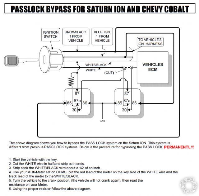
I have modified the diagram posted in the pdf above to what I will be doing to permanently bypass the PASS LOCK on this car.  To do this with the 555L, I would still need two relays because this car does not have a crank wire at the ignition switch.  The crank signal is determined to be when the brown wire is at 0V while the blue wire is at 12V  (see diagram in first post to see how that happens).  This way I just use the two relays and the system is bypassed for good with a 1% tolerance resistor.  I will try this either this or next weekend and will get back to you guys on how it worked. 

Explanation:

When you insert the key into the ignition both relays are off and the white wire gets a 12V signal for key sense.  Once you turn it to igntion, both relays turn on and you will have 5V on the white wire (like its supposed to).  Once you crank the car, only the relay on the right is on and you will have 5V thru resisor on the white wire (which will create some other voltage depending what is on the other end...).   So this basically replicates the function of the ignition switch, but since these go bad so much I will rely on this to work. 

2004 Saturn Ion Passlock II Bypass -- posted image.

If anyone can see a simpler way of accomplishing this (with one relay for example), please let me know.  The key sense wire is not crucial, only that the wire goes between 5V during ignition to 5V thru resisor during crank but again the ion does not have a crank wire at the ignition switch. 

Krysolma 
Member - Posts: 14
Member spacespace
Joined: January 29, 2005
Posted: July 13, 2010 at 9:30 PM / IP Logged  
Confirmed!  I did the install about two weeks ago and everything has been good since. 
saturn03 
Member - Posts: 1
Member spacespace
Joined: October 06, 2010
Posted: October 06, 2010 at 1:38 AM / IP Logged  
I was tired of the Saturn Ion passlock issue and used the steps listed on http://moontaj.com/passlock to solve it.
I was going to try the full bypass but didn't want to risk have no theft protection.
Krysolma regarding your solution, you don't need to cut the white wire. It's risky and from what I hear damages the BCM by permanently setting it into failsafe mode. Following your steps your could have skipped the relays altogether. Cutting the white wire with the engine running disables Passlock but causes other issues. I think the better approach is to remove a battery cable and let the car sit for 10 minutes so you can't trigger the airbag. Then get to the ignition switch. You can pull the white and black wire from the connector (in a way it can be re-inserted later) and tap in to the white, brown and blue wires. One relay's coil is connected between the blue wire and ground and the other is connected between the brown wire and ground (as in your diagram). The WHITE/ black wire gets connected to a proper 1% resistor and the common contact relay powered by the blue wire. The NO contact then connects to the common terminal of the other relay. The NC contact of the second relay then connects to the white wire. Bypassing in this manner allows all features to still function, breaks nothing and is reversible.
I would opt for a solid state solution as relays do fail but trying to weigh the probabilities perhaps not. Relays may have a limited lifetime but they're robust, especially in a harsh automotive environment.
Page of 2

  Printable version Printable version Post ReplyPost New Topic
You cannot post new topics in this forum
You cannot reply to topics in this forum
You cannot delete your posts in this forum
You cannot edit your posts in this forum
You cannot create polls in this forum
You cannot vote in polls in this forum

  •  
Search the12volt.com
Follow the12volt.com Follow the12volt.com on Facebook
Wednesday, April 24, 2024 • Copyright © 1999-2024 the12volt.com, All Rights Reserved Privacy Policy & Use of Cookies
Disclaimer: *All information on this site ( the12volt.com ) is provided "as is" without any warranty of any kind, either expressed or implied, including but not limited to fitness for a particular use. Any user assumes the entire risk as to the accuracy and use of this information. Please verify all wire colors and diagrams before applying any information.

Secured by Sectigo
the12volt.com spacer
Support the12volt.com
Top
the12volt.com spacer