the12volt.com spacer
icon

puddle lighting?


Post ReplyPost New Topic
< Prev Topic Next Topic >
oldspark 
Gold - Posts: 4,913
Gold spacespace
Joined: November 03, 2008
Location: Australia
Posted: July 06, 2010 at 8:58 PM / IP Logged  
Yeah - watch those L O N G posts - it gives Aussies a bad name.
(That's a LOL - see MY replies!!! Though I do give Aussie forums "a bad name" for other reasons (which is why I don't go near them!).
I don't see the need for the relays, but I'll re-read & re-check....
And I'll leave my diagram till later....
I think if you want what I think you want, you'll require a dimmer for each puddle. That's for a real cool "all on with unlock & fading if unopened when unlock unlatches, but remains or turns on if its door is opened, and fades out when closed".
That will still use the door switches but is otherwise independent of the dome light/s.
And congrats - I am not considering this bling as I normally would - this has practical & IMO desirable functionality combined with good HFE (human behavior) attributes.
However I reserve the right to be wrong in the latter and preceding paragraph-blocks!
Also IMO this is one of those projects that should use PICs etc. Though if dimmers aren't expensive, cost- & complexity-wise, discrete (non-PIC or uPC) may still be more attractive.
How much did your dimmer circuit cost?
And does it per chance use PWM (Pulse Width Modulation) aka "digital switching" or chopping to dim rather than analog means (as in varying the current/voltage into a transistor to vary its gain & hence dim)?
My cheap dimmer was merely a $2 2N3055 transistor with a few R's & C's. It's good, but being analog can get quite hot whilst dimming (over ~10 seconds).
And there is no guarantee that 4 such dimmers would be matched in dimming rate. (Hey man - being totally kool excludes mismatched dimming rates!)   
But I'll have to re-read, search & find before I can offer more.
[PS & FTR, I recently purchased 2 Arduino Duemilanoves after deciding (1) they are cheaper & (2) [for me] easier or much less complicated & (3) far less restricted than PICs and a popular PIC assembly I was considering - ie, ~$35 each - and available locally.]
24inchranger 
Member - Posts: 19
Member spacespace
Joined: July 03, 2010
Location: Australia
Posted: July 06, 2010 at 11:00 PM / IP Logged  
Lol on the long post my iPhone almost went into cardiac arrest try to load your one.
As far as the dome delay it Is on the jaycar website I think it just uses a cap which just discharges over Time which is also adjustable with trimpot and a transistor to rapid off if 12v is sensed at ignition It uses the negative side of the switch only to run. Obviously if ignition is on and door open and shuts the light will cone on and off like originaly before circuit.
This is being designed so all areas of the car light up at unlock like dome light so and hazzards ie. Water rocks midgets etc. Can be seen while on approach then when u get in an out only doors that have been opened previously will light preserving other doors the part I am having most trouble with is...
Latching to dome circuit at unlock all external and internal lights on and resetting after internal goes out if no one goes near car obviously both happens at lock.
Disconnecting above circuit and resetting it until another -ve unlock pulse is recieved providing independant lighs trigered by doors also independant of dome because that will be staying on an fading out a per usual.
I forgot to mention that it is by no means bling becuae the lights are all white
oldspark 
Gold - Posts: 4,913
Gold spacespace
Joined: November 03, 2008
Location: Australia
Posted: July 06, 2010 at 11:55 PM / IP Logged  
OMG! Now I know why those color-blind toughies punched the crap out of me - they couldn't see the colors and when I shouted "... ... bling ...!" I didn't realise white was ok!
I'm just glad as heck it was them and not their boyfriends! Phew - my bad. I should crawl back and apologise.... (Why do Aussies shoot things? 'Ave ya seen their girlfriends?)
Jaycar - the $19.95 KC5392? Hmmm - wonder what the 6-pin chip is - a PWM for a heatsunk FET? Nah - probably just an opto-coupler to handle + or - switching, and it's just a transistor....
Later....
24inchranger 
Member - Posts: 19
Member spacespace
Joined: July 03, 2010
Location: Australia
Posted: July 07, 2010 at 1:15 AM / IP Logged  
I now have to resort to using my computer to post the sarcasm meter on my phone just blew my phone up. Lol:)
24inchranger 
Member - Posts: 19
Member spacespace
Joined: July 03, 2010
Location: Australia
Posted: July 07, 2010 at 1:17 AM / IP Logged  
I'll scan the info sheets that came with the kit if you want it all also be found on silicon chip but costs money for the issue
oldspark 
Gold - Posts: 4,913
Gold spacespace
Joined: November 03, 2008
Location: Australia
Posted: July 07, 2010 at 3:51 AM / IP Logged  
LOL! I have May and July 2004!!!
Just like someone wanting an OBDII reader circuit - February 2010 - I think I have every other month!
And yes, you'll learn - short posts & me.... not on!
24inchranger 
Member - Posts: 19
Member spacespace
Joined: July 03, 2010
Location: Australia
Posted: July 12, 2010 at 7:42 AM / IP Logged  
hey oldspark
have you found any circuits i could use
Thanks
oldspark 
Gold - Posts: 4,913
Gold spacespace
Joined: November 03, 2008
Location: Australia
Posted: July 12, 2010 at 9:13 AM / IP Logged  
Not sure if that's a trick question....
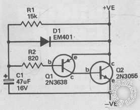
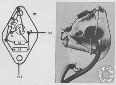
But yes - as just posted in interior light dimming to off (page 2 - July 12, 2010 at 2:37 PM), the following from "Simple Projects from Electronics Today" page 85 (Published 1975):
The circuit:
puddle lighting? - Page 2 -- posted image.
And its birdsnest layout:
puddle lighting? - Page 2 -- posted image.
See interior light dimming to off for more details....
24inchranger 
Member - Posts: 19
Member spacespace
Joined: July 03, 2010
Location: Australia
Posted: July 13, 2010 at 10:23 PM / IP Logged  
Oldspark I'm having trouble with my interior delay not working properly unless it gets 12v from the -ve side of the light which would require me to have a filament bulb but I have led festoon and it's output is about 10v do you think I could put a diode after the + input to the fet going to the caps and run a hot 12v source after the diode because it's only sending the light to ground or would that stop the cap discharging and the circuit would never work
thanks
oldspark 
Gold - Posts: 4,913
Gold spacespace
Joined: November 03, 2008
Location: Australia
Posted: July 13, 2010 at 11:46 PM / IP Logged  
No... (if I understand right)
The dimmer circuit requires a filament bulb to be in series with it and the supply. (IE - +12V thru bulb thru dimmer to GND; or +12V thru dimmer thru bulb to GND.)
In either case, the switch that controls the bulb is connected across the dimmer. (IE - the switch shorts the dimmer.)
A LED does not provide enough current for the dimmer to work. (A LED is ~20mA verses a over 250mA for >3W bulb(s).)
You might be able to substitute a 5W 47Ohm or larger resistor for the bulb, but the LED (in parallel with the 5W resistor) probably won't dim properly. (IMO LEDs require current manipulation to dim properly.)
A diode will NOT work because if it conducts, it is close enough to a short circuit and something will blow (fuse, diode or dimmer).
The circuit DEPENDS on the resistance of the bulb to limit the current whilst providing enough for dimmer circuit operation.
LOL - If only I produced those voltage-ramped PWM dimmers - a dime a dozen and applicable universally (LEDs, lamps, AC, DC).
Page of 3

  Printable version Printable version Post ReplyPost New Topic
You cannot post new topics in this forum
You cannot reply to topics in this forum
You cannot delete your posts in this forum
You cannot edit your posts in this forum
You cannot create polls in this forum
You cannot vote in polls in this forum

  •  
Search the12volt.com
Follow the12volt.com Follow the12volt.com on Facebook
Saturday, May 4, 2024 • Copyright © 1999-2024 the12volt.com, All Rights Reserved Privacy Policy & Use of Cookies
Disclaimer: *All information on this site ( the12volt.com ) is provided "as is" without any warranty of any kind, either expressed or implied, including but not limited to fitness for a particular use. Any user assumes the entire risk as to the accuracy and use of this information. Please verify all wire colors and diagrams before applying any information.

Secured by Sectigo
the12volt.com spacer
Support the12volt.com
Top
the12volt.com spacer