the12volt.com spacer
icon

1980 chevy corvette power antenna wiring


Post ReplyPost New Topic
< Prev Topic Next Topic >
ben d. 
Member - Posts: 36
Member spacespace
Joined: June 08, 2008
Location: Pennsylvania, United States
Posted: July 07, 2010 at 8:41 PM / IP Logged  

Ok guys,  So I have a customer coming in to my shop that needs to get a working power antenna in his 1980 chevy corvette.  It had an aftermarket originally and it was hood installed without a doubt.  What happened was the radio died and so did the power antenna.  He bought a new radio and had our shop put the radio in.  I currently work as an MECP certified tech at best buy.  So new radio goes in without too much of an issue.  I ran new speaker wire and power ground and what not, soldered and heat shrinked it all and now it looks great and the radio works great.  Downside was when it was at my shop he had no power antenna at all.  So i informed the custy that we will hook it up but no real gaurantees since there may be further problems.  Well he put in a new power antenna that he got direct from GM and guess what it doesn't work.

So I had it in the shop an hour before close tonight and here's what I determined.  The wiring that I did was fine and I verified much the same as i did on original install that the relay for the power antenna is activated by the radio.  Radio is a kenwood just so everyone knows.  The downside is still no power antenna working.  There is a relay that controls the power antenna functions and it is underneath the jack storage box.

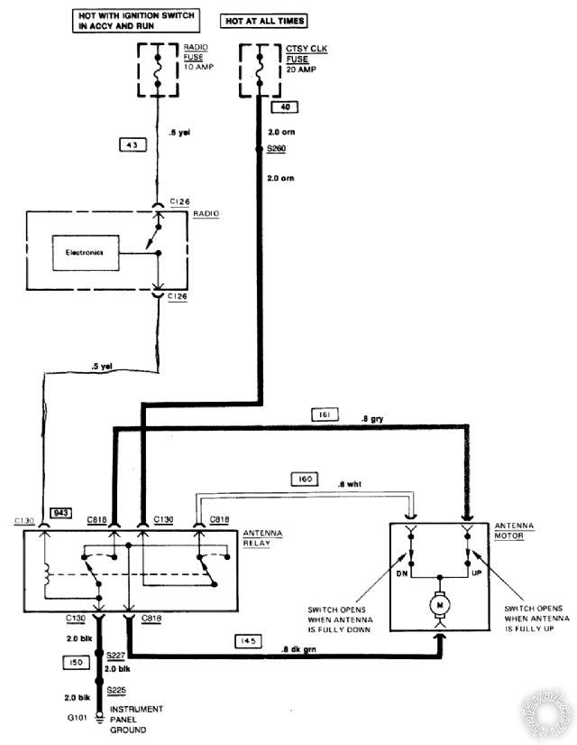
From what I can tell the relay has a total of six wires being connected to it.  This relay does not appear to be like a standard SPDT relay in looks but functionality wise it is the same.  There are three wires on one plug that I will call the input side.

It contains an Orange wire which I tested has no voltage to it at all as of now

A yellow wire which is what is connected to the power antenna trigger of the radio

and a black wire which is ground.

There is then an "output" side of the relay that goes to the power antenna three wires again

Green, this tested as continuous to ground with no voltage.

A gray wire which tested as no voltage with relay active or not and it does not test continuous with the orange wire with relay active or not.

A white wire which tests as no voltage relay active or not, this wire tests continuous with the orange wire when relay is non active and is not continuous with relay active

So my main question here is can anyone inform me what the proper conditions for these wires will be to make the antenna function properly.  My assumption is that the gray wire should be connected to constant power as well as the orange wire and the green is ground.  I tried this with one amp fuses inline from the battery since the battery is only six inches from this relay and all that would happen is popped fuses.  Now I am fully aware it probably takes more than one amp to power the antenna but until I'm sure that's what I need to do I'm not willing to just guess.  For all I know the relay may be bad but I can not online or anywhere find the wiring diagram for this power antenna relay..  GM's factory manuals only show what the wiring plugs into not the statuses.  IF anyone has any tips please pass them forward.  This customer is a very awesome person and I really wanna help them out.  Now I did check all fuses and they test good but for all I know it may be missing fuses once again no real diagrams so I don't know nor is there labeling so yea. 

2008 Dodge Ram 1500
MECP Certified Advanced Installer CEA 191700
mo12v 
Platinum - Nominee - Posts: 2,748
Platinum - Nominee spaceThis member consistently provides reliable informationspace
Joined: September 30, 2003
Location: Afghanistan
Posted: July 07, 2010 at 9:09 PM / IP Logged  

Sounds like the Factory Relay to me

Maybe I misunderstood:

Why mess around with it & just wire direct "IF" you are installing another Antenna

Factory wires

1980 chevy corvette power antenna wiring -- posted image.

MO
Don't Learn from Others Mistakes
You Might Be the One That Knows.
ben d. 
Member - Posts: 36
Member spacespace
Joined: June 08, 2008
Location: Pennsylvania, United States
Posted: July 07, 2010 at 11:45 PM / IP Logged  

beautfiul the diagram is exaclty what I'm looking for.  I would plan on bypassing it but the new antenna that the custy bought is identical to a factory and just plugs in with the factory wiring.  The three wires coming out of that antenna / that are plugged into the factory harness that goes to the relay are the gray, white, green.  I didn't know what needed to go to each wire to actually enable the antenna to go up.  Like I said I had tried to apply power to one of the wires with a 1 amp fues inline but repeatedly it popped the fuse and I was unable to actually get the antenna to even make a sound or move.  I didn't wanna just hook it up with a heavier fuse and then end up buring the antenna or anything else so that's why I wanted a factory diagram.  I mean I was pretty sure I was right with where I was going but I wanted the factory diagram to confirm before just hooking things up, since nothing works at this point there's really nothing to meter and determine it it's almost as if nothing is working at all but either way that diagram is exaclty what I wanted and I will just hook it up the way that diagram describes and done.

It's a damn simple job I mean the wiring is right behind the driver's seat under the carpet and is just right there I just wanted to be certain of the wiring before going to town on it.  TY very much though this is exactly what I was looking for.

2008 Dodge Ram 1500
MECP Certified Advanced Installer CEA 191700
sparkie 
Platinum - Posts: 2,061
Platinum spacespace
Joined: November 06, 2003
Location: Canada
Posted: July 08, 2010 at 6:32 PM / IP Logged  
The orange wire at the relay should have battery power on it. Back in those days GM would fuse it along with the cigarette lighter socket. The sockets would eventually short out, corrode or get a coin in them and blow the fuse.
sparky
ben d. 
Member - Posts: 36
Member spacespace
Joined: June 08, 2008
Location: Pennsylvania, United States
Posted: July 09, 2010 at 7:57 PM / IP Logged  

See that's what appears to be the issue there are quite a few issues in the vehicle with respect to accessory/battery power items.  It appears that the vehicle had a sub-par restoration done at one point and the issues from the work are beginning to surface.  When you look up into the underdash it is apparent it is not factory there is lots of stuff just going everywhere.

The radio I pulled out was just drawing constant power from being jammed in with a fuse so.. as you guys know that's pro.

I'm going to verify relay function with the output wires to the antenna and if all indicates good I will jump the orange wire to the battery..  I have some ten gauge with fuse holders chillin as extra's in the bay  and hopefully that is all that is needed to solve the problem.  Once again guys I appreciate the help

2008 Dodge Ram 1500
MECP Certified Advanced Installer CEA 191700
televise 
Member - Posts: 1
Member spacespace
Joined: October 08, 2010
Posted: October 08, 2010 at 1:47 AM / IP Logged  
I have a GM Power antenna, one of the older ones from te 80's cars andI'm trying to find where they mounted the relay on their cars.  I kmow what it looks like and all but I don't where to look for it on the GM cars.  I took the antenna out of a chevy van, any idea where I would find the relay mounted?

Sorry, you can NOT post a reply.
This topic is closed.

  Printable version Printable version Post ReplyPost New Topic
You cannot post new topics in this forum
You cannot reply to topics in this forum
You cannot delete your posts in this forum
You cannot edit your posts in this forum
You cannot create polls in this forum
You cannot vote in polls in this forum

  •  
Search the12volt.com
Follow the12volt.com Follow the12volt.com on Facebook
Friday, April 26, 2024 • Copyright © 1999-2024 the12volt.com, All Rights Reserved Privacy Policy & Use of Cookies
Disclaimer: *All information on this site ( the12volt.com ) is provided "as is" without any warranty of any kind, either expressed or implied, including but not limited to fitness for a particular use. Any user assumes the entire risk as to the accuracy and use of this information. Please verify all wire colors and diagrams before applying any information.

Secured by Sectigo
the12volt.com spacer
Support the12volt.com
Top
the12volt.com spacer