the12volt.com spacer
icon

528t wiring


Post ReplyPost New Topic
< Prev Topic Next Topic >
blkrhyno 
Copper - Posts: 71
Copper spacespace
Joined: August 16, 2008
Location: New York, United States
Posted: August 05, 2010 at 7:05 PM / IP Logged  
So what I'm trying to do is operate my power folding mirrors when I turn on the ignition and fold in when I shut the ignition off. I have it working but it blows the fuses attach to the power wires. Here is how I have them wired.
528t wiring -- posted image.
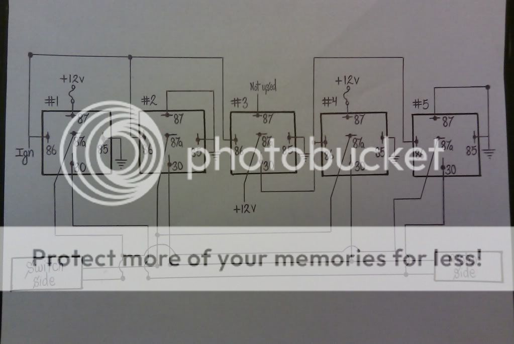
Sorry about the bad drawing, can any tell me what I did wrong. The car is an 04 Audi A6 and I tap in to the wires directly at the mirrors themselves.
Protect what's yours.
hotwaterwizard 
Silver - Posts: 1,350
Silver spacespace
Joined: December 11, 2003
Location: California, United States
Posted: August 05, 2010 at 10:39 PM / IP Logged  

WOW you made it too complicated. Start out with this basic circuit and substitute the Timers Where the switch is. The switch is probably the same as your existing switch for your mirrors in the car.

528t wiring -- posted image.

John DeRosa (Hotwaterwizard)
Stockton California
When in doubt, try it out !
hotwaterwizard 
Silver - Posts: 1,350
Silver spacespace
Joined: December 11, 2003
Location: California, United States
Posted: August 05, 2010 at 10:47 PM / IP Logged  
WE MAY BE ABLE TO SIMPLIFY  it more when I get more time
John DeRosa (Hotwaterwizard)
Stockton California
When in doubt, try it out !
blkrhyno 
Copper - Posts: 71
Copper spacespace
Joined: August 16, 2008
Location: New York, United States
Posted: August 05, 2010 at 11:46 PM / IP Logged  
Thanks for your response wizard but one motor wire has to get +12v and the other gets ground at the same time to open and close. In the diagram above the motor gets +12v one time and ground the other.
Protect what's yours.
howie ll 
Pot Metal - Posts: 16,466
Pot Metal spacespace
Joined: January 09, 2007
Location: United Kingdom
Posted: August 06, 2010 at 10:34 AM / IP Logged  
1st 528t, cut blue loop, BLACK/ white to ignition, orange to switch side of motor opening wire, yellow to mirror side.
2nd 528t BLACK/ white again to ignition, orange to switch side of motor closing wire, yellow to mirror side. (obviously cut both wires)
Brown and red on both to shared 10amp fuse, 12v+ constant feed, blacks to ground. set timers to 4-5 secs. Job done.
blkrhyno 
Copper - Posts: 71
Copper spacespace
Joined: August 16, 2008
Location: New York, United States
Posted: August 06, 2010 at 1:43 PM / IP Logged  
Thanks Howie, I'll try that
Protect what's yours.
blkrhyno 
Copper - Posts: 71
Copper spacespace
Joined: August 16, 2008
Location: New York, United States
Posted: August 09, 2010 at 10:21 AM / IP Logged  
So howie your solution seem to work but I think the mirror motors are burnt out so I'll get new ones and let you know for sure, thanks again
Protect what's yours.
dualsport 
Silver - Posts: 983
Silver spacespace
Joined: September 27, 2005
Location: United States
Posted: September 26, 2010 at 11:28 AM / IP Logged  
blkrhyno wrote:
So what I'm trying to do is operate my power folding mirrors when I turn on the ignition and fold in when I shut the ignition off. I have it working but it blows the fuses attach to the power wires. Here is how I have them wired.
528t wiring -- posted image..
Just poking around here, and thought thought I'd toss a comment in-
Didn't look into the setup in any detail but noticed it would energize the relays in the standby condition, assuming the +12V is wired to be constant rather than switched.
The last two relays are turned on when the ignition is off (relay #3 is off) so they'll be always drawing power. Generally a bad idea to set things up with relays powered on with the car off, since it'll drain out the battery if not started regularly.
Hotwater's diagram switches only one relay at a time, so the motor does get 12V and ground at the same time, and switches polarity depending on which relay is on. It's more failsafe since there's no chance of a short between 12V and ground no matter what relay sequencing or timing is used.
Aside from the standby current draw, your circuit shows a race condition where you're momentarily shorting 12V to ground when you first turn the ignition on, because relay #1 will switch 12V to a grounded line. You may want to rework the circuit-
howie ll 
Pot Metal - Posts: 16,466
Pot Metal spacespace
Joined: January 09, 2007
Location: United Kingdom
Posted: September 26, 2010 at 12:16 PM / IP Logged  
The biggest problem here is we don't know about the factory switch!!!
Ref. Hotwater Wizard's post, the mirrors would normally use a DPDT switch!
On Toyotas, I use 1 x 528t triggered by door lock for the timing plus 2 x mini relays as relay interrupt or "5 wire" because BOTH motor wires are disconnected at rest. This will close the mirror on door lock. As soon as ignition is turned on mirror unfolds.
If motor wires are grounded at rest you would only need a single 528t.
dualsport 
Silver - Posts: 983
Silver spacespace
Joined: September 27, 2005
Location: United States
Posted: September 26, 2010 at 4:51 PM / IP Logged  
Yeah, I didn't look much into the details of what's required, but just wanted to point out the probable reason for the fuses blowing as he described, and that it's going to result in relays being energized when the car is off..
In any case, it'll need to be changed from the present set up.
Page of 2

  Printable version Printable version Post ReplyPost New Topic
You cannot post new topics in this forum
You cannot reply to topics in this forum
You cannot delete your posts in this forum
You cannot edit your posts in this forum
You cannot create polls in this forum
You cannot vote in polls in this forum

  •  
Search the12volt.com
Follow the12volt.com Follow the12volt.com on Facebook
Friday, March 29, 2024 • Copyright © 1999-2024 the12volt.com, All Rights Reserved Privacy Policy & Use of Cookies
Disclaimer: *All information on this site ( the12volt.com ) is provided "as is" without any warranty of any kind, either expressed or implied, including but not limited to fitness for a particular use. Any user assumes the entire risk as to the accuracy and use of this information. Please verify all wire colors and diagrams before applying any information.

Secured by Sectigo
the12volt.com spacer
Support the12volt.com
Top
the12volt.com spacer