the12volt.com spacer
icon

relay to control exhaust cutouts


Post ReplyPost New Topic
< Prev Topic Next Topic >
green can 
Member - Posts: 7
Member spacespace
Joined: September 10, 2010
Posted: September 10, 2010 at 4:30 PM / IP Logged  

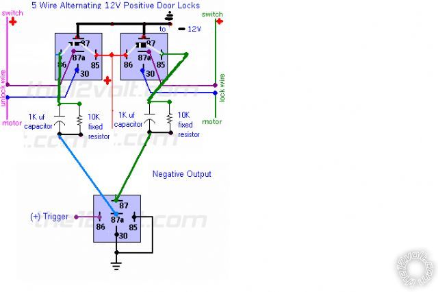
i have 2 jegs elect exhaust cut outs that i want to control via atemp sensor the switch that came with the kit is a rocker switch and both legs are hot at all times.     keeps amps from going thru switch     switches the ground on 1 leg or the other when rocker switch is moved when not moved both wires going to cut outs are hot all the time     will this diagram work for my application       also i need a 1 sec pulse so what res/cap do i needrelay to control exhaust cutouts -- posted image.

dualsport 
Silver - Posts: 983
Silver spacespace
Joined: September 27, 2005
Location: United States
Posted: September 13, 2010 at 4:30 PM / IP Logged  
Can't quite figure out what you're looking for here- what kind of temp sensor were you planning on using, and when is the exhaust cutout supposed to be activated? Is this to open up the exhaust when something gets hot?
Why do you need a 1 sec pulsed output?
dualsport 
Silver - Posts: 983
Silver spacespace
Joined: September 27, 2005
Location: United States
Posted: September 13, 2010 at 4:38 PM / IP Logged  
So it looks like your exhaust cutouts are just a motor controlled valve that open and close based on the polarity of the input, like a window motor, which is what led you to the window circuit-
The question then becomes what is the temp sensor you were going to use, and how. From there you can condition the signal appropriately to do what you want.
green can 
Member - Posts: 7
Member spacespace
Joined: September 10, 2010
Posted: September 13, 2010 at 5:43 PM / IP Logged  
185 degree temp  and yes to open up the cutouts 1 sec because it takes 1 sec to open them when i push the switch
green can 
Member - Posts: 7
Member spacespace
Joined: September 10, 2010
Posted: September 13, 2010 at 5:58 PM / IP Logged  

yes they are a basic motor control valve that i want to open/close with the switch the came with and i want them to open when my 185 tep tells them to and close when temp cools down

my question is what cap/res i need for a 1 sec pulse and can my neg wires switch back and forth going to the capactiors like i have them

im going to radio shack 2 morrow to get cap /resistors  wowever im really confused on the resistors colors and what the colors mean                  i read about them on this site and now im really confused 

i looked up a 10 fixed resistor online and there is many difrent 10k s  out there?

dualsport 
Silver - Posts: 983
Silver spacespace
Joined: September 27, 2005
Location: United States
Posted: September 13, 2010 at 9:45 PM / IP Logged  
Is this temp sensor you're talking about actually a temperature switch that closes to ground above 185 degrees? That would be the first thing to check before going on further. So you want the exhaust cutout to actuate when the switch turns on, and close up again when it cools off?
green can 
Member - Posts: 7
Member spacespace
Joined: September 10, 2010
Posted: September 13, 2010 at 10:30 PM / IP Logged  

yes ihe temp switch is a open close hi limit switch for pressure washers                                                     

my pressure washing van uses a hydraluic clutch pump off the van engine / burns half the fuel a 13 hp honda does    in return works a hyd water pump@ 3500 psi im using exhaust cutouts on my exhaust for my heat exchanger free heat  the heat exchanger works gr8 heats up 6gpm with no problem   

   1 cutout opens as 1 is closed       all engine heat bypasses factory exhaust and goes thru heat exchanger if water gets to hot then it needs to close and then go thru factory exhaust as not to become a bomb or blow a hose up

    the problem is when im not pulling on the triger   the water gets over 200 super fast and the pressure jumps up and will set off the 4500 psi blow out disc

dualsport 
Silver - Posts: 983
Silver spacespace
Joined: September 27, 2005
Location: United States
Posted: September 14, 2010 at 7:54 AM / IP Logged  
Interesting application-
How critical is the pulse time for switching the cutouts open and closed? And how often does this cycle? As long as the switch doesn't cycle too fast, to allow enough time for the circuit to reset for the next pulse.
You need a pretty large cap to get a one second pulse time, the actual time is affected by the relay coil draw. It's simpler to do it like this, but you might consider using a transistor driver instead, so it won't need the large caps. Also it makes it much more easily adjustable. With the direct drive setup, then only way to adjust the timing is to buy another big cap, if it turns out the pulse isn't enough to cycle the cutouts fully. Depends how much you want to avoid using solid state components.
You could just try to find a larger cap like 4700uF and experiment with the relays you're using, and see if the timing will work out okay. You'll probably want to go double the time it needs to cycle the cutouts, just to make sure they close fully.
green can 
Member - Posts: 7
Member spacespace
Joined: September 10, 2010
Posted: September 14, 2010 at 8:38 AM / IP Logged  

i would guess 5 min between pulses main goal is not to burn out the motor on the cutouts as they were $250       like any other elect motor if i keep trying to make it turn when it cant via full open or full closed it will burn up

what is a transistor driver ? where do i get them? and this does sound like what i need

thanks for your help

dualsport 
Silver - Posts: 983
Silver spacespace
Joined: September 27, 2005
Location: United States
Posted: September 14, 2010 at 6:33 PM / IP Logged  

No problem with 5 minutes, so you should be good there. 

Definitely don't want to have the motor drive current get locked on when it's already at the stops, but is there any problem if it gets a partial pulse, and doesn't close fully one way or the other?  Would that cause the cutout valve to burn up also?  I'd guess that could be just as bad.

As far as the transistor driver,  you could build a circuit pretty cheaply, but if you haven't worked with electronic circuits, you might look into using one of the timer modules that are commercially available, just to play it safe.

It'll cost a bit more than a DIY circuit, but might be a better way to go to reduce the risk of something failing and locking up on you.  One of the regular guys here like howie, KP, spark, or iam are more familiar with the particulars and probably could point to the best source for the timer modules, which you'd use to get a momentary output when it gets a transition trigger. 

The momentary output is what you'd use to drive the relays in your circuit to switch the motor current, and you'd need two separate timer modules, one for each relay.

Page of 2

  Printable version Printable version Post ReplyPost New Topic
You cannot post new topics in this forum
You cannot reply to topics in this forum
You cannot delete your posts in this forum
You cannot edit your posts in this forum
You cannot create polls in this forum
You cannot vote in polls in this forum

  •  
Search the12volt.com
Follow the12volt.com Follow the12volt.com on Facebook
Tuesday, April 23, 2024 • Copyright © 1999-2024 the12volt.com, All Rights Reserved Privacy Policy & Use of Cookies
Disclaimer: *All information on this site ( the12volt.com ) is provided "as is" without any warranty of any kind, either expressed or implied, including but not limited to fitness for a particular use. Any user assumes the entire risk as to the accuracy and use of this information. Please verify all wire colors and diagrams before applying any information.

Secured by Sectigo
the12volt.com spacer
Support the12volt.com
Top
the12volt.com spacer