the12volt.com spacer
icon

connecting w2w and d2d on dlpk


Post ReplyPost New Topic
< Prev Topic Next Topic >
danieljaluise 
Copper - Posts: 125
Copper spacespace
Joined: January 19, 2003
Location: United States
Posted: December 11, 2010 at 9:43 AM / IP Logged  
backstory:
I am trouble shooting some strange problems in new install, 2006 impala, viper 5701, dlpk bypass. All the functions work (including starting), but I am getting some strange symptoms: power locks will *sometimes* pulse more than once, DIC will sometimes say "service theft deterrent system" and fail to start, horn and siren will sometimes chirp when arming/disarming. I'm now thinking this may be caused by having both the d2d and w2w wires connected.
qusetion:
can I have the d2d and w2w connections at the same time, or just one? If so, I choose w2w. So what wires will I need to cut from that 4 pin d2d connector? I tried cutting the wires it said in the dlpk manual and could not get the LED on the DLPK to light up. What pins need to see 12v/ground?
sean11901 
Copper - Posts: 118
Copper spacespace
Joined: March 05, 2010
Posted: December 11, 2010 at 9:51 AM / IP Logged  

in my opinion i always do W2W because D2D is fairly new and i dont yet trust it 100%.

you can only use either W2W or D2D. using both im sure will trigger some type of problems.

if you are going to do the W2W you will have to cut the end of the D2D plug that connects into the Remote start and eave the other end plugged into the DLPK.

now the only 2 wires your gonna need from that 4 wire plug is the blue and black. the blue will go to 12V and the black will go to ground.

the from there just make sure you make all of the W2W connections correctly and do not forget to connect  the (-) while running status Blue/white wire from the remote start to the DLPK.

danieljaluise 
Copper - Posts: 125
Copper spacespace
Joined: January 19, 2003
Location: United States
Posted: December 11, 2010 at 11:44 AM / IP Logged  
Thanks! hooked up w2w now, seems to be working ok. Only problem is I am getting a single chirp and 3 flashes on the led when arming the alarm...indicating the door trigger. I verified this as the cause by temporarily disconnecting the green (-) door trigger input from the H1 harness. Weird, because I did diode isolate all 4 doors, and I double checked the orientation of the diodes.
sean11901 
Copper - Posts: 118
Copper spacespace
Joined: March 05, 2010
Posted: December 11, 2010 at 12:14 PM / IP Logged  
DOOR TRIGGER  BCM is located to the left of the steering column

 @ BCM, PINK Plug

are you sure you hooked it up the the correct wires try connecting them to the bcm's pink plug:

The DRIVERS DOOR is a GRAY/BLACK (-) Pin 10,

 the PASSENGER DOOR is a TAN/WHITE (-) Pin 8,

 the DRIVERS REAR DOOR is a BLUE/BLACK (-) Pin 15

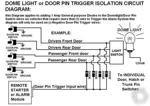
and the PASSENGER REAR DOOR is a LIGHT GREEN/ BLACK (-) Pin 14, use all (4) wires and Diode Isolate as shown in the diagram. 

just think of the light switch as the Bcm in your case:

(AND MAKE SURE THE WHITE BANDS ON THE DIODES ARE FACING THE DOOR TRIGGER WIRES NOT THE ALARM/REMOTE START)

connecting w2w and d2d on dlpk -- posted image.

danieljaluise 
Copper - Posts: 125
Copper spacespace
Joined: January 19, 2003
Location: United States
Posted: December 11, 2010 at 7:51 PM / IP Logged  
Thanks for the help!
I double checked the door trigger connections again.... there are two gray/black wires in the pink plug at the BCM, pin 1 and pin 10. I had the wrong one connected! Switched to the correct wire and everything is good.

Sorry, you can NOT post a reply.
This topic is closed.

  Printable version Printable version Post ReplyPost New Topic
You cannot post new topics in this forum
You cannot reply to topics in this forum
You cannot delete your posts in this forum
You cannot edit your posts in this forum
You cannot create polls in this forum
You cannot vote in polls in this forum

  •  
Search the12volt.com
Follow the12volt.com Follow the12volt.com on Facebook
Saturday, April 27, 2024 • Copyright © 1999-2024 the12volt.com, All Rights Reserved Privacy Policy & Use of Cookies
Disclaimer: *All information on this site ( the12volt.com ) is provided "as is" without any warranty of any kind, either expressed or implied, including but not limited to fitness for a particular use. Any user assumes the entire risk as to the accuracy and use of this information. Please verify all wire colors and diagrams before applying any information.

Secured by Sectigo
the12volt.com spacer
Support the12volt.com
Top
the12volt.com spacer