the12volt.com spacer
icon

2005 crown vic, viper 5101


Post ReplyPost New Topic
< Prev Topic Next Topic >
mortal798 
Member - Posts: 2
Member spacespace
Joined: January 04, 2011
Location: Michigan, United States
Posted: January 04, 2011 at 6:43 PM / IP Logged  

2005 crown vic, viper 5101 -- posted image.Hi everybody,

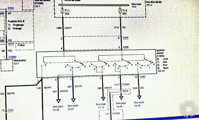
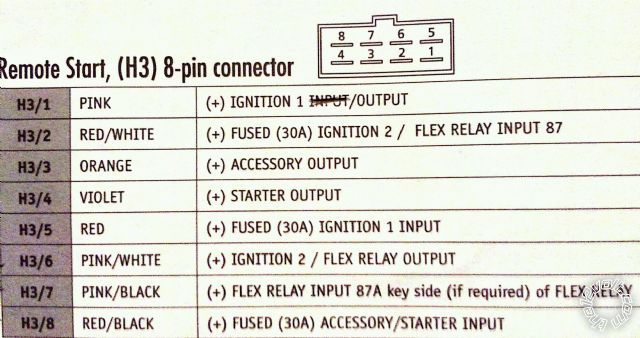
I am new here and I have a question.  I am trying to install a Viper 5101 into a 2005 Crown Vic.  Everything seems to match up correctly, but the vehicle cranks and will not start.  I am using virtual tach.  I have tried a hardwired tach signal, but it doesn't seem to work either way.  I think I may have some of the H3 Harness wired incorrectly.  I am including a pic of the Ford wiring diagram of the ignition switch, and the Viper 5101 H3 harness wiring.  Can someone please tell me which H3 wires go to which wires on the vehicle?  Thanks for your time!2005 crown vic, viper 5101 -- posted image.

tonanzith 
Gold - Posts: 593
Gold spaceThis member consistently provides reliable informationspace
Joined: July 18, 2008
Location: Washington, United States
Posted: January 04, 2011 at 7:00 PM / IP Logged  
h3/1 goes to PURPLE / orange
h3/2 goes to red (25A)
h3/3 goes to gray / YELLOW
h3/4 goes to dk. green
h3/5 goes to red (25A)
h3/6 goes to WHITE/ lt. blue
h3/7 not used
h3/8 goes to red (25A)
You will need to make sure to program the alarm so that the flex relay is set to ACCESSORY not IGNITION.
ALSO you will notice that there are 3 accessory wires for your vehicle and you only have 1 in the h3 harness PLUS the 2nd from the flex relay when programmed to accessory. You will need to use a relay to power the 3rd accessory wire. Tap the signal from the h3/3 wire and send it to pin 86 of the relay. Send ground to pin 85. connect pin 87 to the red (25a) and then pin 30 to WHITE/ purple of your vehicle. This will power the 3rd ignition during remote start. FAILING to do this can cause malfunctions and check engine lights.
Gary Sather
mortal798 
Member - Posts: 2
Member spacespace
Joined: January 04, 2011
Location: Michigan, United States
Posted: January 04, 2011 at 9:47 PM / IP Logged  

Thanks!  I got it figured out - had to switch two wires.  Also had to hardwire the tach, virtual didn't work.  I hooked right in to the CKP+ at the PCM C175E Pin 34 BK/PK.

Works great!  Thanks again!


Sorry, you can NOT post a reply.
This topic is closed.

  Printable version Printable version Post ReplyPost New Topic
You cannot post new topics in this forum
You cannot reply to topics in this forum
You cannot delete your posts in this forum
You cannot edit your posts in this forum
You cannot create polls in this forum
You cannot vote in polls in this forum

  •  
Search the12volt.com
Follow the12volt.com Follow the12volt.com on Facebook
Tuesday, April 23, 2024 • Copyright © 1999-2024 the12volt.com, All Rights Reserved Privacy Policy & Use of Cookies
Disclaimer: *All information on this site ( the12volt.com ) is provided "as is" without any warranty of any kind, either expressed or implied, including but not limited to fitness for a particular use. Any user assumes the entire risk as to the accuracy and use of this information. Please verify all wire colors and diagrams before applying any information.

Secured by Sectigo
the12volt.com spacer
Support the12volt.com
Top
the12volt.com spacer