the12volt.com spacer
icon

how to replace vac/starter switch?


Post ReplyPost New Topic
< Prev Topic Next Topic >
arizonaclassic 
Member - Posts: 6
Member spacespace
Joined: December 31, 2009
Location: Arizona, United States
Posted: January 10, 2011 at 10:11 AM / IP Logged  

I am working on a 1960 Buick convertible. Originally these cars had a feature that starts the car by turning the ign. to "on" and pressing the gas pedal. This system used a switch mounted to the carb to activate that starter.  The switch is disabled when the vehicle is running by a built-in vac. switch (a tube from the switch down into the carb which holds a spring and ball) and by a relay that senses output from the generator. I need to keep this function working.

What I have done so far is; convert the car to use an alternator instead of a generator and installed dual four barrel carbs instead of a single four barrel. In place of the original carb mounted switch, which is not interchangable with the new carbs, I installed a throttle position switch which is normally used to activate a NOS system. 

I believe I have wired the alt. to send the correct signal to the relay that shuts down that starter switch, but I can't figure out how to add the second shut down signal. Basicly I need to have the switch disabled when the car is running so the starter is not engaged everytime the pedal is pressed. It originally thought I would use a vac. sensing switch, but I can't find one. Another option might be a rpm sensing switch or something.

Anyone have input that would help me finish this? If so, item descriptions, part numbers, and suppliers would be very helpful as I am still learning this skill. Thanks in advance. 

oldspark 
Gold - Posts: 4,913
Gold spacespace
Joined: November 03, 2008
Location: Australia
Posted: January 10, 2011 at 10:35 PM / IP Logged  
Why not use the alternator signal - ie, the charge light.
It's the same as electric fuel-pump circuits and battery isolators (the UIBI refers) but with an SPDT relay.
IE - use the NC contacts to normally connect the starter.
The charge lamp (circuit) energises the relay hence opening the contacts.
If you are referring to a backup signal (in case the alternator fails), fuel pumps also used spark sensing.
EFI systems could also use an air flap switch if the ECU didn't control the fuel pump relay.
Though maybe a manual disable switch is easier....
resquchas 
Copper - Posts: 93
Copper spacespace
Joined: April 15, 2010
Location: Virginia, United States
Posted: January 11, 2011 at 1:03 PM / IP Logged  
I think Oldspark is right about the manual disable switch. It sounds like so much has been changed already. I understand the novelty, specializing in restoring cars from many decades, but often older systems were the best at THAT time. Today other options MAY be more practical. I do appreciate the engineering though.
The RIGHT way is the ONLY way.
oldspark 
Gold - Posts: 4,913
Gold spacespace
Joined: November 03, 2008
Location: Australia
Posted: January 11, 2011 at 1:59 PM / IP Logged  
Thanks resquchas. You said it well. Er, wrote it well....
The original system is one I'd fit a 2-way switch for to allow for mechanism failure - one to inhibit starting (with the throttle), one to start (if connection to carby switch etc fails).
[ It makes me think of my mum's dash LED voltmeter - on (with IGN), off, and momentary on (for voltage check without IGN) - a 3PST switch; 2-position latching plus momentary. ]
These days there are so many ways of imitating original functionality but with superior mechanisms. And making the transparent....
But many old systems have rightfully been discontinued.
[ Yet again, that old PITA oil-pressure control of electric fuel pumps comes to mind. I found it amazing that it was used by some as an OEM "backup" for normal ECU control! Talk about failing to protect the engine (which is what those using oil pressure THINK they are doing LOL!) ]
And as for some things, there is no going back. EG - alternators with internal regulators. Forget external regulators; certainly electro-mechanical ones! And my ute's original generator and Bendix-spring starter - ha!
But my 45 year old ute is my everyday vehicle which does more than the average yearly mileage (~15Mm or ~10k miles).   
[ Mind you, I used to have an external electronic regulator disguised as the standard relay version. And if keep on originality, I could "convert" an old genny, or and old dizzy to electronic (rather than a chopped late 1970s dizzy with mid-1980s electronic guts). And no one see's the Bendix nor the clutch diaphragm spring.... ]
Ooops - please forgive my rambling hijack.
I merely wanted to thank resquchas and support his comment. (Note resquchas's signature!)
There are many ways of improving on original designs - especially tailoring such switching logic or functionality to better suits ones needs. [ EG - fitting an override or disconnect switch to Stability Controls, auto-wipers, auto-lights, and ABS LOL! ]
arizonaclassic 
Member - Posts: 6
Member spacespace
Joined: December 31, 2009
Location: Arizona, United States
Posted: January 12, 2011 at 2:08 PM / IP Logged  

Thank you for your advice.  I too believe that old technology is old technology.  In this case, I can understand why Buick stopped using this method of starting the car after only a few years. If the generator signal fails and/or if the car is running with little vacuum it is possible to engage the starter while the engine is running. Also if the throttle switch is not adjusted correctly the car will recieve too much or too little fuel before the engine turns over which will cause no start or flooding.  

I agree that a manual disable switch is the safest and definently the most reliable security measure for this application, but I have been over-ruled on it's use.  We are 3 years and at least $70K into this car and will probably end somewhere over $100K.  The owner does not like the idea of having to flip a switch every time he starts the car, so I'm back to looking for options on disabling the switch while the car is running.

I will definently try to use the 'GEN' light (which is now the ALT. warning light) to control a kill relay.  I will have to do some re-reading on the alternator/starter solenoid/relay system.  I am still fighting that warning light after the generator to alternator conversion.  I have converted all of the original instrument cluster lights to LED lights and that one was staying on all the time.  I believe it is a resistance issue, but I guess that may end up as a forum question somewhere else later.

Thanks again. 

oldspark 
Gold - Posts: 4,913
Gold spacespace
Joined: November 03, 2008
Location: Australia
Posted: January 12, 2011 at 5:20 PM / IP Logged  
arizonaclassic wrote:
The owner does not like the idea of having to flip a switch every time he starts the car....
Ah - the classic MORON that does not understand an emergency fallback as opposed to NORMAL EVERYDAY USE!
So just use the alternator output for both and he can call for road assistance if it ever fails.
Then all of us are happy!
If this results from money, then buy the original parts or commission a copy.
oldspark 
Gold - Posts: 4,913
Gold spacespace
Joined: November 03, 2008
Location: Australia
Posted: January 12, 2011 at 5:47 PM / IP Logged  
PS....
The normal alternator wiring is SIMPLE.
The charge lamp circuit is simply a change-over relay in the alternator's regulator which is normally ground but switches to +12V when it is charging.
Hence it grounds the HOT charge lamp when not charging, and can energise grounded relays when it is charging.
EG:
how to replace vac/starter switch? -- posted image.
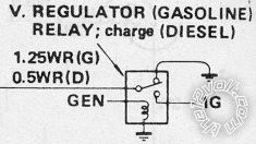
(From Chilton's else similar references; the LHS "output" goes to the charge-Lamp's ground and can supply +12V to energise N.C. fuel cut valves, or N.O. fuel-pump relays, auto-chokes and idle-solenoids etc, or headlight or load or battery isolators etc.)
It is commonly used to control electric fuel pumps on older vehicles, and UIBIs (Ultimate Intelligence Battery Isolators) by modern clever people, etc.
But BEWARE - the charge lamp (else other parallel lamps or resistances) are usually required to supply a tickle or trickle current to ENSURE the alternator initiates charging. (Otherwise the alternator relies on remnant rotor magnetism to start charging, though some regulators will simply not initiate without this trickle current (eg - Bosch S&L types).)   
The other issue is alternator type & vintage.
Older external electo-mech regulators have no problems sinking lamp currents or sourcing relay currents.
Electronic regulators (external or internal) can usually sink an Amp or two, and usually supply and Amp or two, but it isn't guaranteed. (EG - most alternators from the 1970s thru 1990s would sink an Amp or two from dash bulbs.)
Modern vehicles may have low-current or asymmetric interfaces - use a transistor, FET or MOSFET instead else as a buffer.   
Or they may be EMS interactive in which case any charge lamp "circuit" is used instead (ie, lamp on when NOT charging as with normal charge lamps), else ANYTHING that changes state when charging or not charging (eg voltage or current sensing circuits).
It sounds difficult but it isn't. It is only the changing technology since vehicle generators wee introduce that changes HOW we use that information - ie, that the system is charging.

Sorry, you can NOT post a reply.
This topic is closed.

  Printable version Printable version Post ReplyPost New Topic
You cannot post new topics in this forum
You cannot reply to topics in this forum
You cannot delete your posts in this forum
You cannot edit your posts in this forum
You cannot create polls in this forum
You cannot vote in polls in this forum

  •  
Search the12volt.com
Follow the12volt.com Follow the12volt.com on Facebook
Sunday, May 5, 2024 • Copyright © 1999-2024 the12volt.com, All Rights Reserved Privacy Policy & Use of Cookies
Disclaimer: *All information on this site ( the12volt.com ) is provided "as is" without any warranty of any kind, either expressed or implied, including but not limited to fitness for a particular use. Any user assumes the entire risk as to the accuracy and use of this information. Please verify all wire colors and diagrams before applying any information.

Secured by Sectigo
the12volt.com spacer
Support the12volt.com
Top
the12volt.com spacer