the12volt.com spacer
icon

Field Disturbance vs. Proximity Sensor


Post ReplyPost New Topic
< Prev Topic Next Topic >
cpgoose 
Gold - Posts: 1,098
Gold spacespace
Joined: July 08, 2002
Location: United States
Posted: April 25, 2003 at 7:51 AM / IP Logged  
Hi...
I recently got a DEI 508T Field Disturbance Sensor, and have been trying to find some information on here about it. What I keep finding instead is info on the 508D Proximity Sensor. Is there a major difference between these two?
What (I think) I've found is that the 508D is a 4-wire module, and my 508T is a three wire (red, black, and blue). So does this mean that mine is just a one-stage module, and the 508D is a dual-stage?
Thanks for any help. Just trying to figure out how to patch this into an existing trigger wire (the blue multi-plex one).
krazypolishboy 
Member - Posts: 17
Member spacespace
Joined: January 25, 2003
Location: United States
Posted: April 27, 2003 at 1:20 AM / IP Logged  
yes, the 508d is a dual stage sensor, i just put mine in the other night, works great
cpgoose 
Gold - Posts: 1,098
Gold spacespace
Joined: July 08, 2002
Location: United States
Posted: April 27, 2003 at 4:00 PM / IP Logged  
Well, for installing this sensor....can I hook up it's blue wire to the alarm's blue wire? If I did this, I guess I need a diode there too, with the stripe on the diode going towards the alarm, correct?
I guess I'm also trying to figure out how to make this work with warn away and with a full blown alarm? If this module is just a one-stage, is there a way to make it two stage by hooking it up to the shock sensor?
Thanks guys!
krazypolishboy 
Member - Posts: 17
Member spacespace
Joined: January 25, 2003
Location: United States
Posted: April 27, 2003 at 9:00 PM / IP Logged  
You should match up all of the colors on the proximity sensor to the wire colors of the shock sensor. i didnt use any diodes on mine. The 508D has black, red, blue, and green wires, while the 508t just has the black, red, and blue. the green wire on the 508d is what is the sensor uses to send either a .3 second (i might be wrong) pulse, or the full .8 second(might be wrong again on the timing) pulse to trigger a full alarm. i dont think you can make it work as a two stage sensor, since whenever it detects a disturbance in the set field it is going to send the signal for full alarm, it doesnt have the capability to send just a warn away signal. you might want to go back and get the 508D if you really want a dual stage sensor. what kind of alarm are you running it off of?
cpgoose 
Gold - Posts: 1,098
Gold spacespace
Joined: July 08, 2002
Location: United States
Posted: April 28, 2003 at 6:18 AM / IP Logged  
Yea, I got the 508t cheap, so I figured I'd just mess with it. I was curious that if I hook up the blue wire from the 508t to the green wire on the shock sensor (the wire that supposedly give the .3second pulse) I could get the warning chirps rather than the full blast. (Then, in theory, if it chirped long enough...or was activated 3 times, then maybe I would get the full blast?) This is just me wishing and hoping, but I don't think it's correct.
cpgoose 
Gold - Posts: 1,098
Gold spacespace
Joined: July 08, 2002
Location: United States
Posted: April 29, 2003 at 9:51 AM / IP Logged  
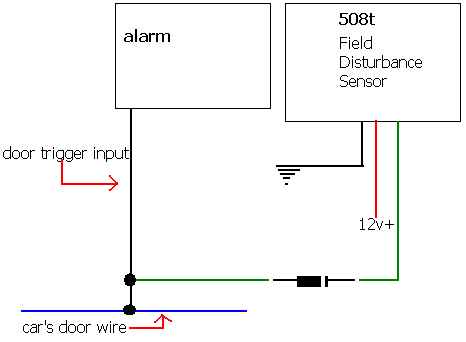
Well, can someone tell me if this diagram is correct? I was going to connect the green wire of the sensor to the door trigger input wire. I was also going to put a diode on that sensor's wire, with the stripe facing the sensor. Is this correct? I'm assuming there's no way to get a pre-warn, and then a full blast, since this is only a one-stage device?
THANKS!
Field Disturbance vs. Proximity Sensor -- posted image.
Velocity Motors 
Moderator - Posts: 12,488
Moderator spaceThis member has made a donation to the12volt.com. Click here for more info.spaceThis member has been recognized as an authority in Electrical Theory. Click here for more info.spaceThis member has been recognized as an authority in Fabrication. Click here for more info.spaceThis member has been recognized as an authority in Mobile Audio and Video. Click here for more info.spaceThis member has been recognized as an authority in Mobile Security and Convenience. Click here for more info.spacespace
Joined: March 08, 2002
Location: Manitoba, Canada
Posted: April 29, 2003 at 11:09 AM / IP Logged  

Hey CP, don't use the door trigger instead use the hood pin trigger. WHY ? The door will be either a (-) or a (+) trigger and if the diode is not large enough it will feedback into the (-) trigger sensor and end up shorting out the sensor. The 508T is a (-) trigger output so installing the GREEN wire with the diode band facing the hood pin wire will make the diagram work out. Does this make sense ?

Jeff
Velocity Custom Home Theater
Mobile Audio/Video Specialist
Morden, Manitoba CANADA
cpgoose 
Gold - Posts: 1,098
Gold spacespace
Joined: July 08, 2002
Location: United States
Posted: April 29, 2003 at 11:20 AM / IP Logged  
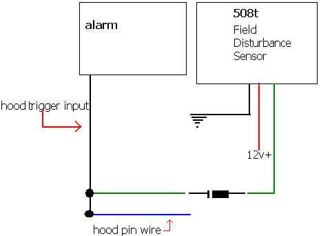
Thank you so much! Here's another diagram just to double check :-) The band on the diode is facing the hoodpin wire so that current won't flow back into the sensor, correct?
As for making this dual-stage with the shock sensor, that's not possible, is it?
Field Disturbance vs. Proximity Sensor -- posted image.
Velocity Motors 
Moderator - Posts: 12,488
Moderator spaceThis member has made a donation to the12volt.com. Click here for more info.spaceThis member has been recognized as an authority in Electrical Theory. Click here for more info.spaceThis member has been recognized as an authority in Fabrication. Click here for more info.spaceThis member has been recognized as an authority in Mobile Audio and Video. Click here for more info.spaceThis member has been recognized as an authority in Mobile Security and Convenience. Click here for more info.spacespace
Joined: March 08, 2002
Location: Manitoba, Canada
Posted: April 29, 2003 at 11:55 AM / IP Logged  
Yes, the diagram is correct. You can install the 508T trigger wire to the impact sensor's final trigger wire and it will work. Go here for hookin up the perimeter sensor to the impact sensor. The only thing is you can not use the impact sensors warn away withthis set up.
Jeff
Velocity Custom Home Theater
Mobile Audio/Video Specialist
Morden, Manitoba CANADA
cpgoose 
Gold - Posts: 1,098
Gold spacespace
Joined: July 08, 2002
Location: United States
Posted: April 29, 2003 at 12:23 PM / IP Logged  
Thanks Jeff...I would have had the diode going the other way by mistake :-) I'll try it with the hoodpin trigger first. If the full alarm goes off too much, maybe I'll change things around.
Thanks for the help!
Page of 2

  Printable version Printable version Post ReplyPost New Topic
You cannot post new topics in this forum
You cannot reply to topics in this forum
You cannot delete your posts in this forum
You cannot edit your posts in this forum
You cannot create polls in this forum
You cannot vote in polls in this forum

  •  
Search the12volt.com
Follow the12volt.com Follow the12volt.com on Facebook
Saturday, June 8, 2024 • Copyright © 1999-2024 the12volt.com, All Rights Reserved Privacy Policy & Use of Cookies
Disclaimer: *All information on this site ( the12volt.com ) is provided "as is" without any warranty of any kind, either expressed or implied, including but not limited to fitness for a particular use. Any user assumes the entire risk as to the accuracy and use of this information. Please verify all wire colors and diagrams before applying any information.

Secured by Sectigo
the12volt.com spacer
Support the12volt.com
Top
the12volt.com spacer