the12volt.com spacer
icon

avital 4111 issue


Post ReplyPost New Topic
< Prev Topic Next Topic >
sgarcia1212 
Member - Posts: 40
Member spacespace
Joined: October 08, 2010
Location: California, United States
Posted: June 27, 2011 at 8:52 AM / IP Logged  
Hi all,
Avital 4111 installed in 2003 accord. I want to connect the rear defogger/defrost but the (-200mA Blue w/white while car is running) output from the unit is being usu for an xpresskit (PKALL) that my car requires. is there another way to add the rear defogger/defroster to this unit?
thanks in advance.
sgarcia1212
howie ll 
Pot Metal - Posts: 16,466
Pot Metal spacespace
Joined: January 09, 2007
Location: United Kingdom
Posted: June 27, 2011 at 10:50 AM / IP Logged  
Split the wire and diode both lines, 1N4004, in line bands towards alarm.
Unless there's a second status (GWR) output wire.
thecoolmankyle7 
Copper - Posts: 77
Copper spacespace
Joined: April 25, 2011
Posted: June 27, 2011 at 12:09 PM / IP Logged  
You could also use an aux output set to latched. Then you could turn it on when you need it. Either way will work great.
lectricguy 
Copper - Posts: 359
Copper spacespace
Joined: March 18, 2008
Location: Rhode Island, United States
Posted: June 27, 2011 at 8:26 PM / IP Logged  

There is a 4 pin satellite harness that has a status output--I believe it is the Blue wire; hook that status output to your PKALL.   This will allow you to free up your Blue/White wire so it can be used for activating the rear defogger.

Lectric Guy
sgarcia1212 
Member - Posts: 40
Member spacespace
Joined: October 08, 2010
Location: California, United States
Posted: June 27, 2011 at 9:34 PM / IP Logged  
All was a lot of help, but I used Lectric Guy way. Now I have the additional status wire but I still have a problem. 10 sec After the rs starts the voltage on the wire connected to the defroster drops from 14v to 1.7v when it kicks in, and I don't see the defroster light come on. When I measure the voltage on the defroster wire and turn it on manually the voltage drops from 12.3v to 0.17v
Any ideas guys?
Thanks an advance.
sgarcia1212
sgarcia1212 
Member - Posts: 40
Member spacespace
Joined: October 08, 2010
Location: California, United States
Posted: June 27, 2011 at 9:49 PM / IP Logged  
Update: the output is set to latch. The 14v are there when the car is running.
The 12v were measured with the car off.
Do I need a resistor to be able to drop that signal to 0v?
Thanks.
sgarcia1212
blanx218 
Silver - Posts: 654
Silver spacespace
Joined: September 23, 2008
Location: Pennsylvania, United States
Posted: June 27, 2011 at 10:13 PM / IP Logged  
The 2nd status needs to be programmed to the rear defogger  setting and either pulsed or latched depending on what your vehicle requires. You then have to activate it when you want to use it. check the owners manual for how to do so
sgarcia1212 
Member - Posts: 40
Member spacespace
Joined: October 08, 2010
Location: California, United States
Posted: June 27, 2011 at 10:28 PM / IP Logged  
Blanx218,
I tested both modes and still doesn't work.
For some reason this output is not droping the voltage to 0v.
Somebody help, please.
sgarcia1212
blanx218 
Silver - Posts: 654
Silver spacespace
Joined: September 23, 2008
Location: Pennsylvania, United States
Posted: June 28, 2011 at 12:08 AM / IP Logged  
just checked the manual and it says it comes on 10 seconds after the remote start is activated. Ive seen alot of vehicles that when it activates the defroster the light on the dash doesnt come on but it does turn on the defroster. Try to remote start the car and hold your hand on the rear window and see if it feels like its getting warm. It may be working and you just dont know it.  If not you may need a better ground than the 200mA output and need to use a relay
howie ll 
Pot Metal - Posts: 16,466
Pot Metal spacespace
Joined: January 09, 2007
Location: United Kingdom
Posted: June 28, 2011 at 2:50 AM / IP Logged  
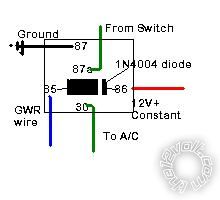
It might need a relay to boost the current.
See diagram:-avital 4111 issue -- posted image..
This assumes at the switch and it's either a pulsed or latched negative going wire. Sorry blanx I was "drawing" this as you posted. Great minds etc.
Page of 2

  Printable version Printable version Post ReplyPost New Topic
You cannot post new topics in this forum
You cannot reply to topics in this forum
You cannot delete your posts in this forum
You cannot edit your posts in this forum
You cannot create polls in this forum
You cannot vote in polls in this forum

  •  
Search the12volt.com
Follow the12volt.com Follow the12volt.com on Facebook
Sunday, May 5, 2024 • Copyright © 1999-2024 the12volt.com, All Rights Reserved Privacy Policy & Use of Cookies
Disclaimer: *All information on this site ( the12volt.com ) is provided "as is" without any warranty of any kind, either expressed or implied, including but not limited to fitness for a particular use. Any user assumes the entire risk as to the accuracy and use of this information. Please verify all wire colors and diagrams before applying any information.

Secured by Sectigo
the12volt.com spacer
Support the12volt.com
Top
the12volt.com spacer