the12volt.com spacer
icon

train horns triggered by alarm


Post ReplyPost New Topic
< Prev Topic Next Topic >
jbroski33 
Member - Posts: 7
Member spacespace
Joined: August 25, 2011
Location: Texas, United States
Posted: August 25, 2011 at 3:15 PM / IP Logged  
Hello all,
I am trying to have my train horns activated when my alarm is triggered. Sometimes they are triggered, but not every time like they should be. Here is what I have done so far: hooked up an on/off switch (so I can choose whether or not to have the air horns triggered by the alarm) to the push button switch which activates the solenoid on the air horns. Also, when I have the on/off in the "on" position, and hit the push button switch to the air horns, the alarm siren goes off.
Any help would be greatly appreciated :)
i am an idiot 
Platinum - Posts: 13,667
Platinum spaceThis member consistently provides reliable informationspace
Joined: September 21, 2006
Location: Louisiana, United States
Posted: August 25, 2011 at 4:29 PM / IP Logged  
You need to place a 1 amp diode in the wire between the siren output and the relay for your train horns. Band of the diode toward the relay.
jbroski33 
Member - Posts: 7
Member spacespace
Joined: August 25, 2011
Location: Texas, United States
Posted: August 25, 2011 at 4:43 PM / IP Logged  
Ok,I see. Thank you for you fast reply. I kind had a feeling I might need a diode somewhere. I will try that first thing in the morning when it's not 500 degrees outside haha Thanks again
i am an idiot 
Platinum - Posts: 13,667
Platinum spaceThis member consistently provides reliable informationspace
Joined: September 21, 2006
Location: Louisiana, United States
Posted: August 25, 2011 at 7:34 PM / IP Logged  
I am just to the right of you. It was only 486 today.
jbroski33 
Member - Posts: 7
Member spacespace
Joined: August 25, 2011
Location: Texas, United States
Posted: August 26, 2011 at 11:20 AM / IP Logged  
Haha I hear ya
jbroski33 
Member - Posts: 7
Member spacespace
Joined: August 25, 2011
Location: Texas, United States
Posted: September 24, 2011 at 1:14 PM / IP Logged  
So, I am still not quite sure how to wire up the train horns correctly, so that they will honk when my alarm shock sensor has been triggered. I would also like to also wire in an on/off switch, so that I can choose to not have the train horns honk with the alarm. If anyone could help me figure out how to do this, I would be eternally grateful. Here is a schematic of my alarm system and a diagram of how my train horn solenoid is wired:train horns triggered by alarm -- posted image.
train horns triggered by alarm -- posted image.
howie ll 
Pot Metal - Posts: 16,466
Pot Metal spacespace
Joined: January 09, 2007
Location: United Kingdom
Posted: September 25, 2011 at 5:44 AM / IP Logged  
Try this:- horn.bmp
Assuming (you haven't mentioned the vehicle) a neg horn push, this will give you the horns from:-
a) The alarm BLACK/ white according to your posted diagram.
b)The vehicle horn push.
c) A separate switch.
Remember to use those diodes, very important.
jbroski33 
Member - Posts: 7
Member spacespace
Joined: August 25, 2011
Location: Texas, United States
Posted: September 25, 2011 at 10:16 AM / IP Logged  
howie ll wrote:
Try this:- horn.bmp
Assuming (you haven't mentioned the vehicle) a neg horn push, this will give you the horns from:-
a) The alarm BLACK/ white according to your posted diagram.
b)The vehicle horn push.
c) A separate switch.
Remember to use those diodes, very important.
Thanks for the help, Howie. Hopefully I will have time to hook that up today, if not it will be next weekend.
I have a 96 Ford Explorer, which is negative horn output from what I can remember
jbroski33 
Member - Posts: 7
Member spacespace
Joined: August 25, 2011
Location: Texas, United States
Posted: October 09, 2011 at 3:25 PM / IP Logged  
Howie,
I was going to try this the other day, but then noticed a few things.. The 85 & 86 on your diagram are backwards.. Is that the correct way? ALso, the diodes: someone in an earlier post said to put the band of the diode towards the relay, but in your pic it is away from the relay. Which is correct?
I also wanted to note that I am not using the vehicle horn button for the train horns, I have a separate SPST (not sure if that matters). Here is a better pic of exactly how it is hooked up right now
Sorry for so many questions, but this is really confusing me, and thanks for everyones help
train horns triggered by alarm -- posted image.
howie ll 
Pot Metal - Posts: 16,466
Pot Metal spacespace
Joined: January 09, 2007
Location: United Kingdom
Posted: October 09, 2011 at 4:32 PM / IP Logged  
No actually I'm correct, you're wrong.train horns triggered by alarm -- posted image.
International convention calls for 85 = neg of coil and 86 = pos!
In practice this doesn't matter except that many relays have inbuilt diodes and car manufacturers will wire the relays that way.
Also my diodes are correct, you're sending neg towards the relay, the diodes are there to prevent feedback especially to the alarm and the bands are correct, trust me....remember I do this for a living!
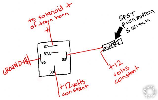
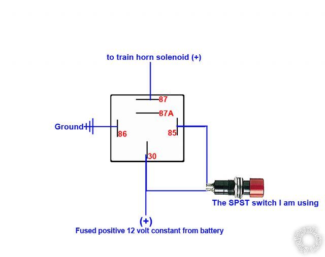
Your last diagram, to make it work with the alarm, put the momentary switch to 85 and ground (0v) the other side of the switch NOT 12v+.
Between the switch and the alarm join the black white from the alarm, not forgetting those diodes.
Run your 12v+ to 30 and 86. Incidentally in a 4 terminal switching relay like you show 30 and 87 ARE interchangeable.
Page of 2

  Printable version Printable version Post ReplyPost New Topic
You cannot post new topics in this forum
You cannot reply to topics in this forum
You cannot delete your posts in this forum
You cannot edit your posts in this forum
You cannot create polls in this forum
You cannot vote in polls in this forum

  •  
Search the12volt.com
Follow the12volt.com Follow the12volt.com on Facebook
Thursday, April 25, 2024 • Copyright © 1999-2024 the12volt.com, All Rights Reserved Privacy Policy & Use of Cookies
Disclaimer: *All information on this site ( the12volt.com ) is provided "as is" without any warranty of any kind, either expressed or implied, including but not limited to fitness for a particular use. Any user assumes the entire risk as to the accuracy and use of this information. Please verify all wire colors and diagrams before applying any information.

Secured by Sectigo
the12volt.com spacer
Support the12volt.com
Top
the12volt.com spacer