the12volt.com spacer
icon

nissan rogue, viper 5902 issues


Post ReplyPost New Topic
< Prev Topic Next Topic >
ixanos 
Member - Posts: 4
Member spacespace
Joined: November 13, 2011
Location: New York, United States
Posted: November 26, 2011 at 11:01 AM / IP Logged  
Can someone explain to me how the H3 harness outputs works when the Remote Start command is sent?
I have installed the starter with an XK09 unit. The alarm feature works fine but the car will not remote start. I went through the diagnostics and could not find a solution. I am not getting any power coming out of the Purple wire in the first 2 seconds of the remote start.
In a start sequence is this the order of power
1) Acc
2) Ign 1
3) Start?
Thx
kreg357 
Platinum - Posts: 7,783
Platinum spaceThis member has made a donation to the12volt.com. Click here for more info.spaceThis member has been recognized as an authority in Electrical Theory. Click here for more info.spaceThis member has been recognized as an authority in Mobile Security and Convenience. Click here for more info.spacespace
Joined: January 30, 2009
Location: Pennsylvania, United States
Posted: November 26, 2011 at 2:01 PM / IP Logged  

H3/1 PINK (+) IGNITION 1 INPUT/OUTPUT                                    Pink @ Ignition Switch Harness

H3/2 RED / WHITE (+) FUSED (30A) Flex Relay                              Blue @ Ignition Switch Harness
H3/3 ORANGE (+) ACCESSORY OUTPUT                                      Pink @ Ignition Switch Harness
H3/4 VIOLET (+) STARTER OUTPUT (CAR SIDE)                         Red @ Ignition Switch Harness
H3/5 GREEN (+) STARTER INPUT (KEY SIDE)                              Red @ Ignition Switch Harness
H3/6 RED (+) FUSED (30A) IGNITION 1 INPUT                              Blue @ Ignition Switch Harness
H3/7 PINK/WHITE (+) FLEX RELAY OUTPUT                                  Brown @ Ignition Switch Harness    *** Set Viper Menu3, Item8, Opt2 for ACC2
H3/8 PINK/BLACK (+) FLEX RELAY INPUT 87A                              N.U.
H3/9 RED / BLACK (+) FUSED (30A) ACC/STARTER INPUT         Blue @ Ignition Switch Harness
H3/10 NC (no connection)                                                                   N.U.

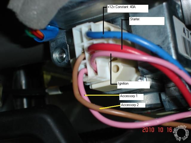
Here is a picture of the ignition harness with the wires marked  :

nissan rogue, viper 5902 issues -- posted image.

Please note that there are two Pink wires.  One is / tests as Igntion1 and the other is / tests

as an Accessory.

Soldering is fun!
ixanos 
Member - Posts: 4
Member spacespace
Joined: November 13, 2011
Location: New York, United States
Posted: November 27, 2011 at 5:07 PM / IP Logged  
Thanks Kreg357,
I think the original installer may have blew out the circuit that powers up the relay that switches the power to the ignition and start circuit.
I connected H3 exactly as above. I went through page 22 of the Viper 5902 Installation guide.
1) Check voltage on the purple wire (H2/13) two seconds after the remote start becomes active = Zero Voltage (not good), so I went to step 2.
2) Check the 30A fuses = All good.
3) Check Gray/black wire (H2/7) = Zero Volts => Good.
4) I disconnected the tach wire (Pin 1 violet//white wire on PK09 to H2/9 violet/white). I get zero volts on the gray/black wire (H2/7) => Good.
Is it possible that the output for the start relay and ignition relay are burnt out and does not turn on in the 5902 and this is why I am not getting power out on H2/13 purple wire?
This is why I am asking the question. What is the sequence of outputs on the H3 connector to check the power (12Volts) at the following terminals.
1) H3/1 - ignition (Gas Pump circuit on Rogue)
2) H3/1 and H3/4 - Power to starter (Crank Starter = 1 second)
3) H3/1 and H3/3 - Accessory 1 and H3/7 Accessory 2
I get power on H3/7 but when the 5902 does not see any tach it tries to start again for a maxiumum of three attempts then I get the low RPM alarm.
Thx
kreg357 
Platinum - Posts: 7,783
Platinum spaceThis member has made a donation to the12volt.com. Click here for more info.spaceThis member has been recognized as an authority in Electrical Theory. Click here for more info.spaceThis member has been recognized as an authority in Mobile Security and Convenience. Click here for more info.spacespace
Joined: January 30, 2009
Location: Pennsylvania, United States
Posted: November 27, 2011 at 6:29 PM / IP Logged  

I'm not sure if you are testing the H2/13 wire correctly.  A Ground output at engine crank is what you should see.  The way to test this wire is with a DMM set to 20V DC, Red lead to +12V constant and Black lead to H2/13.  You will see basically 0 volts until the (-) Starter Output goes true, at which point the meter will show +12v ( because the circuit is now completed ) while it tries to crank.  However this wire is probably not used and while it should indicate what is supposed to happen, the real story is from H3/4. 

The H2/7 Gray/Black wire is the Diesel Wait to Start Input wire.  Not sure what purpose metering that wire will achieve.  Your car is not a diesel and does not use that wire.  It should be properly insulated and neatly tied out of the way.

The Tach signal coming from the bypass module should be OK, but you could try another tach source, like a Fuel Injector.  Always verify with a DMM and do a Tach Learn with the new connection before attempting a remote start.

OK, here is the H3 sequence as I understand it.  Remember there is a lot going on behind the scenes inside the viper.  This info will be specific to your car and the Vipers config.

H3/2, H3/6 and H3/9 all should have constant +12V power.  H3/2 supplies the output power for the Flex relay at H3/7.  H3/6 supplies the output power for H3/1.  H3/9 supplies the output power for H3/4 and H3/3.

When a remote start command is received ( auto trans ), the Viper simultaneously energizes H3/1, H3/3 and H3/7.  This supplies power to your cars one Ignition circuit and both Accessory circuits.  H3/7 ( Flex Relay ) has been programmed via Menu3, Item8, Opt2 to act as an Accessory output.  After a slight delay, the Viper drops power to both Accessory circuits, H3/3 and H3/7, and applies power to H3/4 to crank the engine.  The length of the Starter output depends on how the Viper has been programmed.  Read the install guide for Menu3, Item2 and Item3. Depending on those programmable options, the H3/4 output is dropped and the H3/3 and H3/7 are brought active again ( +12v).

This is a very simplified version of the start sequence.  There are a lot of variables to consider.

A few questions :

Has the system ever worked?
Is the vehicles starter wire cut and the Viper H3/4 & H3/5 connected properly?
Has the XK09 been flashed with the correct firmware and properly wired?
Has the XK09 been successfully programmed to the vehicle?
Did you re-connect the Tach wire after testing?
Does the Viper successfully Tach Learn?
Are there any errors displayed after a failed remote start or info from Shutdown Diagnostics?
Have you tried changing to Virtual Tach ( and disconnecting the Violet/White tach wire )?
Have you tried changing to a fixed crank time?

Soldering is fun!
ixanos 
Member - Posts: 4
Member spacespace
Joined: November 13, 2011
Location: New York, United States
Posted: November 28, 2011 at 10:25 PM / IP Logged  
Your right about the method of testing H2/13. I had my black probe on the chassis and the red probe on H2/13. I did not see a change in voltage before and after the remote start. It look like the output is always grounded. H2/13 is not used in the installation. I was just following the Remote Start Troubleshooting instructions in the 5902 installation guide.
A few questions :
Has the system ever worked?
Is the vehicles starter wire cut and the Viper H3/4 & H3/5 connected properly?
>> Yes, violet to starter and green to key switch.
Has the XK09 been flashed with the correct firmware and properly wired?
>> Yes, flashed NISS02 version 1.05
Has the XK09 been successfully programmed to the vehicle?
>> Yes, did the 5 steps and the LED turned off in step 4.
Did you re-connect the Tach wire after testing?
>> Yes, reconnected the tach wire between the Xk09 and 5902.
Does the Viper successfully Tach Learn?
>> Yes, got the constant Control Center Light after 3 seconds.
Are there any errors displayed after a failed remote start or info from Shutdown Diagnostics?
>> No, only error was the low tach after the three start attempt. (I used to get the MTS mode not enable until Menu 3 item 1 was programmed for Automatic.
Have you tried changing to Virtual Tach ( and disconnecting the Violet/White tach wire )?
>> No I di not try it since I cannot perform step 1: " After the install is complete, remote start the engine."
Have you tried changing to a fixed crank time?
>> Yes, I tried 0.8, 1.0 and 1.2 seconds option.
Is it possible that the ouptut may have been damaged by attaching the H2/13 to the start wire H3/4?
During the initial remote start, I do not get the 12 volts at H3/1 or H3/3 or H3/4.
All I get is the 12 volt pulse on H3/7 during the 3 start attempt by the 5902.
I have given up. All the security functions works. I seriously think the starter circuit for H3/1 and H34 internal relays are damaged so the relays are not changing states.
Based on your description for H3/1, H3/3, H3/4 and H3/7 I have a faulty 5902 remote starter circuit.
My options is either to go to bestbuy to get a new unit installed or buy a second unit.
ixanos 
Member - Posts: 4
Member spacespace
Joined: November 13, 2011
Location: New York, United States
Posted: November 28, 2011 at 10:27 PM / IP Logged  
Sorry, I did not answer your first question: The remote start function never worked but the alarm functions works.

Sorry, you can NOT post a reply.
This topic is closed.

  Printable version Printable version Post ReplyPost New Topic
You cannot post new topics in this forum
You cannot reply to topics in this forum
You cannot delete your posts in this forum
You cannot edit your posts in this forum
You cannot create polls in this forum
You cannot vote in polls in this forum

  •  
Search the12volt.com
Follow the12volt.com Follow the12volt.com on Facebook
Friday, April 19, 2024 • Copyright © 1999-2024 the12volt.com, All Rights Reserved Privacy Policy & Use of Cookies
Disclaimer: *All information on this site ( the12volt.com ) is provided "as is" without any warranty of any kind, either expressed or implied, including but not limited to fitness for a particular use. Any user assumes the entire risk as to the accuracy and use of this information. Please verify all wire colors and diagrams before applying any information.

Secured by Sectigo
the12volt.com spacer
Support the12volt.com
Top
the12volt.com spacer