the12volt.com spacer
icon

2009 mazda 3, python 524


Post ReplyPost New Topic
< Prev Topic Next Topic >
csvt#49 
Member - Posts: 9
Member spacespace
Joined: December 28, 2011
Location: Minnesota, United States
Posted: December 28, 2011 at 9:43 PM / IP Logged  
I've done my digging and I've read quite a bit to the point where I feel I am more then capable of tackling this installation. I have a background in engineering and know my way around mechanical & electronic components and the tools to service them. So don't be afraid to through out deep technical info I can handle it. However that said I have a few questions.
First off I found a DirectWire wire listing for the car off of another site. So I think I'm ahead of the game a little (I've attached a link to the pics below for your review). Although this is my first ever install of a car alarm and remote start system. The Python 5204P model 524 only came with a "quick reference Install Guide" which offers no details for how the inputs/outputs of the control module should be connected. Basically my first goal is to correlate the wires I have on the alarm/remote start with the wires I have from the wiring information off of the DirectWire listing. There are a lot of gaps from what I can see. I also am not 100% certain what connections require relays and what ones do not. Everyone mentions using relays for the door locks to switch polarity and then also a 1kohm resistor for the lock but straight negative for the unlock. However looking at the quick install it shows a (-) already for the polarity on the Python module so I'm not sure if a relay is really needed. So I would assume that if I just put a 1kohm resistor inline on the unlock output I should be good? Then for the trunk release to function installers told me they needed to charge me for a relay install. I'm confused by this as why wouldn't I be able to utilize the relay already in the car for the OEM trunk release? Then one last thing to throw into the mix, I'm installing heated seats on the car and would like to have the remote start kick them on as well. I'm assuming I would just hook the relay from the heater install up to the AUX 1 output on the 24-pin connector of the Python module.
So to recap
-Is the DirectWire information I have below correct (don't see rear defrost)?
-What wires correlate to the alarm/remote start connectors from the DirectWire information?
-What outputs will I need relays for?
-Can I use the outputs on the module to drive the relays already on the car?
Your help is greatly appreciated. Thanks!
Python 524 quick install   
Mazda3 DirectWire information
Page 1
Page 2
-Mike
98 Ford SVT Contour
09 Mazda3
05 EB Expedition
97 Civic DX
csvt#49 
Member - Posts: 9
Member spacespace
Joined: December 28, 2011
Location: Minnesota, United States
Posted: December 28, 2011 at 9:51 PM / IP Logged  
I also forgot to mention I have a PKALL immobilizer bypass to go with this install as well. I found the following install information for that as well. Not really following the install though as I am not sure what "D2D" is.
Mazda3 04-09 PKALL reference
-Mike
98 Ford SVT Contour
09 Mazda3
05 EB Expedition
97 Civic DX
csvt#49 
Member - Posts: 9
Member spacespace
Joined: December 28, 2011
Location: Minnesota, United States
Posted: December 29, 2011 at 7:49 AM / IP Logged  
Alright I figured out the PKALL connections. D2D just stands for Data to Data connection. Looks like the only connection (the one that was clear) I need to make is for "connector 2" and nothing else matters. Still working on trying to correlate wire to wire for the alarm/remote start though.
-Mike
98 Ford SVT Contour
09 Mazda3
05 EB Expedition
97 Civic DX
csvt#49 
Member - Posts: 9
Member spacespace
Joined: December 28, 2011
Location: Minnesota, United States
Posted: December 29, 2011 at 7:55 AM / IP Logged  
I mispoke in my earlier post as I do need one more connection which is "connection 1" this is the D2D connection and is made from the PKALL directly to my Python 524 module with the wire harness included with the PKALL, which makes for a nice easy connection. I would have just edited my last post to explain this... but yea I'm not cool enough to be a standard member yet ;)
-Mike
98 Ford SVT Contour
09 Mazda3
05 EB Expedition
97 Civic DX
csvt#49 
Member - Posts: 9
Member spacespace
Joined: December 28, 2011
Location: Minnesota, United States
Posted: December 29, 2011 at 9:06 AM / IP Logged  
Alright here is my attempt at the wiring schematic correlation (see link below). I'd really appreciate it if someone could look this over and verify I've got this correct. When doing this I did have quesions regarding the starter output inputs as there seems to be a number of locations some of which look to be the same. That said here are the following connections I would like help with (thanks in advance)
Trouble spots - Not sure where to hook up
H3/4 Violet (+) Starter Output (car side)
H3/6 Red (+)Fused (30A) Ign 1 Input *how is this different then H3/1
H3/9 RED / Blk (+)Fused (30A) Accessory/Starter Input
H2/2 Blk/Wht (-)Netural Safety Input *couldn't find on wire info
H2/3 Blu/Wht (-)Rear Defogger Output *couldn't find on wire info
H2/5 RED / wht (-)Trunk Release Output *car has it, but not on wire info
H2/9 Dark Blu (-)Status Output
H2/10 Pink (-)Ign 1 output *again how is this different then H3/1
H2/18 Vlt/Yel (-)Starter Output *same as H3/4??
H2/22 Org (-)Accessory Output *Same as H3/3??
Schematic Markup Link
-Mike
98 Ford SVT Contour
09 Mazda3
05 EB Expedition
97 Civic DX
offroadzj 
Gold - Posts: 2,043
Gold spaceThis member has made a donation to the12volt.com. Click here for more info.spaceThis member has been recognized as an authority in Mobile Security and Convenience. Click here for more info.spacespace
Joined: June 03, 2005
Location: New York, United States
Posted: December 29, 2011 at 9:21 AM / IP Logged  
csvt#49 wrote:
Alright here is my attempt at the wiring schematic correlation (see link below). I'd really appreciate it if someone could look this over and verify I've got this correct. When doing this I did have quesions regarding the starter output inputs as there seems to be a number of locations some of which look to be the same. That said here are the following connections I would like help with (thanks in advance)
Trouble spots - Not sure where to hook up
H3/4 Violet (+) Starter Output (car side) <-- Connect this to your vehicle start wire from the DEI schematic.
H3/6 Red (+)Fused (30A) Ign 1 Input *how is this different then H3/1 <-- They each control different internal relays in the remote start. This needs to see a constant 12v signal.
H3/9 RED / Blk (+)Fused (30A) Accessory/Starter Input <-- Same as above. Constant 12v Signal.
H2/2 Blk/Wht (-)Netural Safety Input *couldn't find on wire info <-- This wire needs to see a ground signal in order for the starter to operate. Ground this wire with your main chassis ground.
H2/3 Blu/Wht (-)Rear Defogger Output *couldn't find on wire info <-- If you really want the rear defrost to come on, you will have to test your factory switch to see which wire shows a temporary ground when the button is pressed.
H2/5 RED / wht (-)Trunk Release Output *car has it, but not on wire info <-- Is it mechanical or electrical? If electrical then you will have to test the factory switch and find out if it is (+) or (-). If (+) it will require a relay.
H2/9 Dark Blu (-)Status Output <-- This wire shows a (-) 200ma signal when the remote start is activated. If using D2D for the PK-ALL then this wire is not used.
H2/10 Pink (-)Ign 1 output *again how is this different then H3/1 <-- This is a (-) 200ma output activated at the same time as your main ignition wire. It is normally not connected.
H2/18 Vlt/Yel (-)Starter Output *same as H3/4?? <-- Same as Pink above.
H2/22 Org (-)Accessory Output *Same as H3/3?? <-- Same as Pink above.
Schematic Markup Link
I answered your questions in the quote. Make sure to test ALL connections and don't just rely on the schematic. If you do not have a good DMM then get one before proceeding. In addition, the wiring diagram I have for that car shows a 2nd accessory wire. I am not 100% certain if it is required for the remote start but hopefully someone can chime in on that one. If so you will connect the heavy gauge pink/white wire to that wire and change the flex relay output to 2nd accessory in the programming options.
Kenny
Owner / Technician
KKD Garage LLC
Albany, NY 12205
csvt#49 
Member - Posts: 9
Member spacespace
Joined: December 28, 2011
Location: Minnesota, United States
Posted: December 29, 2011 at 9:39 AM / IP Logged  
Thanks for the reply Kenny!
So as I was thinking about the starter wires does the remote start break the starter wire on the ignition harness such that the remote start module is wired in-line with the starter wire? I saw your post stating to follow the DEI schematic, but I think the question is still valid.
so something like this...
starter relay----gry/blk----[]----vlt----[Python Module]----grn----[]----gry/blk----ign
-Mike
98 Ford SVT Contour
09 Mazda3
05 EB Expedition
97 Civic DX
csvt#49 
Member - Posts: 9
Member spacespace
Joined: December 28, 2011
Location: Minnesota, United States
Posted: December 29, 2011 at 9:45 AM / IP Logged  
Oh forgot to mention I have a Fluke 77III meter in the electrical drawer of my took box, so I will most definitely be checking all the connections. This my wife's first car she bought so I don't want to be causing problems with it for her.
-Mike
98 Ford SVT Contour
09 Mazda3
05 EB Expedition
97 Civic DX
csvt#49 
Member - Posts: 9
Member spacespace
Joined: December 28, 2011
Location: Minnesota, United States
Posted: December 29, 2011 at 11:28 AM / IP Logged  
I apologize if this questions seem newbish, but I figure a stupid question is the unasked ones.
I also was reading up on another alarm/remote start system that I have, which came with a full detailed installation guide (Viper 5900 SST system). Since this product is very similar to the Python and is also made by DEI I was referencing it. With that system they show that the alarm arm/disarm wires need to be connected to relays. Is this true? I would have thought that this could have been connected directly the the cars factory harness. Or is this because the system is not capable of pulsing the signal and therefore needs the relay to accomplish this? This same thing was mentioned for the dome light supervision output Seems odd to me.
Pics from Viper 5900 install manual:
2009 mazda 3, python 524 -- posted image.
-Mike
98 Ford SVT Contour
09 Mazda3
05 EB Expedition
97 Civic DX
offroadzj 
Gold - Posts: 2,043
Gold spaceThis member has made a donation to the12volt.com. Click here for more info.spaceThis member has been recognized as an authority in Mobile Security and Convenience. Click here for more info.spacespace
Joined: June 03, 2005
Location: New York, United States
Posted: December 29, 2011 at 12:28 PM / IP Logged  
csvt#49 wrote:
Thanks for the reply Kenny!
So as I was thinking about the starter wires does the remote start break the starter wire on the ignition harness such that the remote start module is wired in-line with the starter wire? I saw your post stating to follow the DEI schematic, but I think the question is still valid.
so something like this...
starter relay----gry/blk----[]----vlt----[Python Module]----grn----[]----gry/blk----ign
Yes, for the starter kill / anit-grind feature of the starter, you will cut your factory starter wire and connect the green wire to the switch side of the cut starter wire and the violet to the car side of the cut starter wire.
Kenny
Owner / Technician
KKD Garage LLC
Albany, NY 12205
Page of 2

  Printable version Printable version Post ReplyPost New Topic
You cannot post new topics in this forum
You cannot reply to topics in this forum
You cannot delete your posts in this forum
You cannot edit your posts in this forum
You cannot create polls in this forum
You cannot vote in polls in this forum

  •  
Search the12volt.com
Follow the12volt.com Follow the12volt.com on Facebook
Sunday, May 5, 2024 • Copyright © 1999-2024 the12volt.com, All Rights Reserved Privacy Policy & Use of Cookies
Disclaimer: *
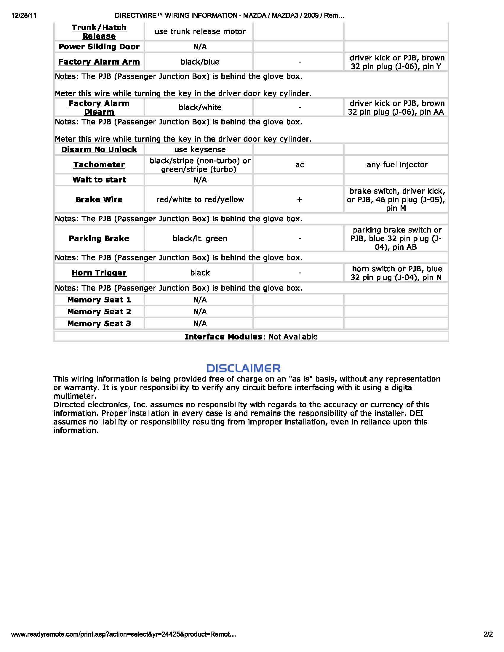
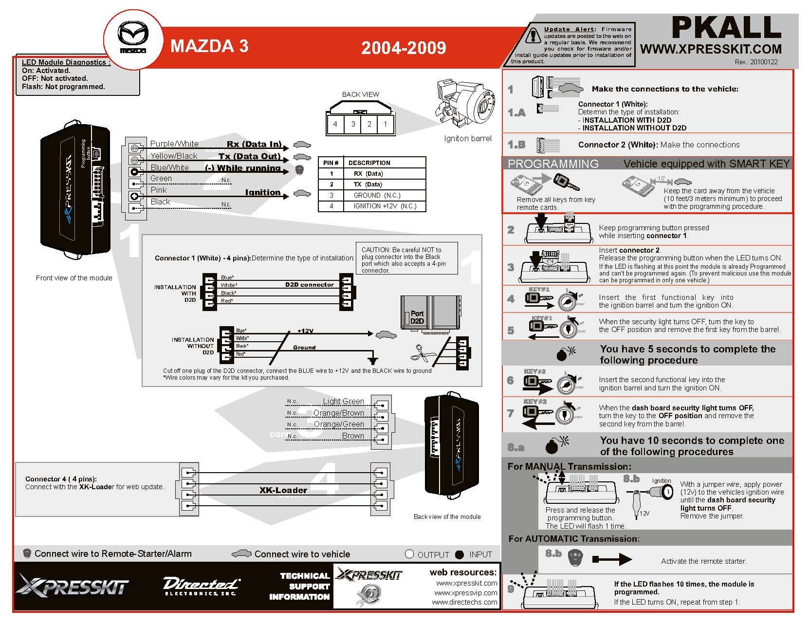
All information on this site ( the12volt.com ) is provided "as is" without any warranty of any kind, either expressed or implied, including but not limited to fitness for a particular use. Any user assumes the entire risk as to the accuracy and use of this information. Please verify all wire colors and diagrams before applying any information.

Secured by Sectigo
the12volt.com spacer
Support the12volt.com
Top
the12volt.com spacer