the12volt.com spacer
icon

puzzled, dpdt relay and sensing


Post ReplyPost New Topic
< Prev Topic Next Topic >
midlifez 
Member - Posts: 6
Member spacespace
Joined: March 14, 2012
Posted: March 15, 2012 at 12:06 PM / IP Logged  

THANKS! Will give it a shot this weekend.

Final questions..

 The configuration you sugges will ensure that in the situation where the cars is ON and the MANUAL switch is moved to the folded position that no short will occur, correct?

midlifez 
Member - Posts: 6
Member spacespace
Joined: March 14, 2012
Posted: March 17, 2012 at 11:19 AM / IP Logged  
midlifez wrote:

howie ll wrote:
Sorry, I did the original some time ago, newer version!
79C_mirror_fold.bmp
On fold run it to an ignition wire and diode with a 1N4004, band towards the ignition.
On the 528t used to OPEN the mirrors, from the ignition side of your first join, run a wire to the open 528t BLACK/ white, this time cut the loop on that 528t and diode 1N4004 the other way round, i.e. band away from ignition.
This will give you close on turning off ignition, open on turning on ignition. Set the 528t internal timers for 1 second longer than it takes to open or fold the mirrors.

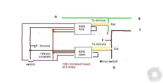
OK, just so I am clear, looking at the last image you posted the connections are as in the image I posted, I enlarged it and labled each connection. Am also confused as I dont see any switch/accessory power connection, i.e. one which is only hot when the car is turned on.

A: Mirror

B: Mirror
C:?
D:Manual mirror switch
E: ?
F: ?

puzzled, dpdt relay and sensing - Page 2 -- posted image.

Sorry to be dense possibly, but want to make sure wire up corectly. In the diagram you posted the colors dont match what the 528t has. On the 528t there are the below color wires, which match to your colors in the diagram above?

Colors are:
528T / Your Diagram
ORANGE /
YELLOW / Yellow
RED /
BLACK / Black (ground)
BLACK with White Stripe / Got this one figured out
BROWN /

howie ll 
Pot Metal - Posts: 16,466
Pot Metal spacespace
Joined: January 09, 2007
Location: United Kingdom
Posted: March 17, 2012 at 2:40 PM / IP Logged  
Orange goes to F and D switch side
Yellow to mirrors(s) side A,B, E$, and C.
Red to fused 12V+ constant source.
Brown joined to red.
Black to ground.
As I've already stated there is no switch, if you want to fold or unfold or override the auto settings use the OEM switch with the kit.
It is switched automatically by the ignition switch going to ground when off (fold) and to 12V+ live when on, open hence the diodes to prevent errors.
Your failing to understand and repeat the switch question makes me wonder as to your competence to achieve this.
Page of 2

Sorry, you can NOT post a reply.
This topic is closed.

  Printable version Printable version Post ReplyPost New Topic
You cannot post new topics in this forum
You cannot reply to topics in this forum
You cannot delete your posts in this forum
You cannot edit your posts in this forum
You cannot create polls in this forum
You cannot vote in polls in this forum

  •  
Search the12volt.com
Follow the12volt.com Follow the12volt.com on Facebook
Thursday, May 8, 2025 • Copyright © 1999-2025 the12volt.com, All Rights Reserved Privacy Policy & Use of Cookies
Disclaimer: *All information on this site ( the12volt.com ) is provided "as is" without any warranty of any kind, either expressed or implied, including but not limited to fitness for a particular use. Any user assumes the entire risk as to the accuracy and use of this information. Please verify all wire colors and diagrams before applying any information.

Secured by Sectigo
the12volt.com spacer
Support the12volt.com
Top
the12volt.com spacer