


safe dual battery w/ half power tap
Home /
the12volt's Install Bay /
General Discussion / safe dual battery w/ half power tap ( Topic Closed)
Welcome Guest :)


Posted: March 22, 2012 at 8:21 PM / IP Logged
Keeping in mind that it's not extra current, but a higher voltage. (Current can't push itself into loads.)
And a higher voltage contradicts the presence of any regulator. (Though inductive circuits could cause a voltage spike, but that shouldn't blow bulbs.)
Oops - I've confused this thread with the VW HID-conversion problem...  This situation may simply be one of no regulation on the AC to the headlight. Maybe back-to-back Zeners would be a solution (2 high-power ~14V zeners diodes?), else converting to dc and limiting.
And a resistor can replace the bulb, though a higher wattage main bulb is equivalent.
But the problem is that the extra loading takes away the limited power available to the main bulb at lower RPM.
Hence a regulator should be used.
And yes, d'oh! - the alternator's light coil/output feeds the separate 35W bulb. (Hence as you say, no battery impact. Brilliant!)
The only concern there is under-voltage to halogens, but I'm shaky on that issue. (As I recall, insufficient voltage/heat causes certain deposits to form hence pre-killing the bulb.)
That's been something I've been meaning to re-investigate to see if PWM dimmers may have a similar detrimental effect.
But unless your higher wattage bulbs fail miserably, I can keep that issue at its current priority. (Or should that be its voltage priority? Damned ambiguous English - but I love its puns!)
That's where a LED solution would be ideal - ample and probably superior lighting at any RPM. (Fit a bridge rectifier and a dc-dc converter.)
If the "12V" batteries are lasting ages, then the simpler total loss system IMO is best.
I'd then suggest your auto recharge system, probably triggered manually in response to a low-voltage warning (though I prefer and still recommend a 3-digit voltmeter; that's my only "bling", but it's IMO well worth it - as I say "voltage tells all") or when you decide you can charge during periods of non-12V use.
But then I come back to a dedicated normal main 6V battery and a dc-dc converter to step up to 12V ($20?, & smaller than any battery) though a small 12V battery could also be fitted.
Then I'd ditch the voltmeter, though I still reckon they should be mandatory - they let you know if there is a charging or overload problem, of if the battery is near its end of life. A push-button or switch could be used to select the default 6V else 12V systems.
I still think I like a dc-dc converter approach. In ye olde days I would have said to expensive & big etc, but those current-logic.com devices were a real eye opener. (With thanks to one of the gifted contributors at mp3car.com!)
A rectifier for the lighting output feeding a dc-dc conv which overcomes any over-voltage bulb blowing and maximises illumination at low RPM.
And a dc-dc conv from the 6V battery to the 12V circuit. (Maybe the 6V battery can be scrapped if there are no 6V loads, but alternator and dc-dc conv input issues need consideration.)
Yep, I like the dc-dc converter approach. Still 2 batteries though 6V & 12V (not 2x 6V), but no complex switching; no unbalanced charging issues, no expensive power-wasting zeners etc; probably smaller and simpler wiring than relays; and probably cheaper - and fully automated. (Converter disconnection when off being the only extra issue, and the added rectifier/diodes for the lighting output.)
This situation may simply be one of no regulation on the AC to the headlight. Maybe back-to-back Zeners would be a solution (2 high-power ~14V zeners diodes?), else converting to dc and limiting.
And a resistor can replace the bulb, though a higher wattage main bulb is equivalent.
But the problem is that the extra loading takes away the limited power available to the main bulb at lower RPM.
Hence a regulator should be used.
And yes, d'oh! - the alternator's light coil/output feeds the separate 35W bulb. (Hence as you say, no battery impact. Brilliant!)
The only concern there is under-voltage to halogens, but I'm shaky on that issue. (As I recall, insufficient voltage/heat causes certain deposits to form hence pre-killing the bulb.)
That's been something I've been meaning to re-investigate to see if PWM dimmers may have a similar detrimental effect.
But unless your higher wattage bulbs fail miserably, I can keep that issue at its current priority. (Or should that be its voltage priority? Damned ambiguous English - but I love its puns!)
That's where a LED solution would be ideal - ample and probably superior lighting at any RPM. (Fit a bridge rectifier and a dc-dc converter.)
If the "12V" batteries are lasting ages, then the simpler total loss system IMO is best.
I'd then suggest your auto recharge system, probably triggered manually in response to a low-voltage warning (though I prefer and still recommend a 3-digit voltmeter; that's my only "bling", but it's IMO well worth it - as I say "voltage tells all") or when you decide you can charge during periods of non-12V use.
But then I come back to a dedicated normal main 6V battery and a dc-dc converter to step up to 12V ($20?, & smaller than any battery) though a small 12V battery could also be fitted.
Then I'd ditch the voltmeter, though I still reckon they should be mandatory - they let you know if there is a charging or overload problem, of if the battery is near its end of life. A push-button or switch could be used to select the default 6V else 12V systems.
I still think I like a dc-dc converter approach. In ye olde days I would have said to expensive & big etc, but those current-logic.com devices were a real eye opener. (With thanks to one of the gifted contributors at mp3car.com!)
A rectifier for the lighting output feeding a dc-dc conv which overcomes any over-voltage bulb blowing and maximises illumination at low RPM.
And a dc-dc conv from the 6V battery to the 12V circuit. (Maybe the 6V battery can be scrapped if there are no 6V loads, but alternator and dc-dc conv input issues need consideration.)
Yep, I like the dc-dc converter approach. Still 2 batteries though 6V & 12V (not 2x 6V), but no complex switching; no unbalanced charging issues, no expensive power-wasting zeners etc; probably smaller and simpler wiring than relays; and probably cheaper - and fully automated. (Converter disconnection when off being the only extra issue, and the added rectifier/diodes for the lighting output.)

Posted: March 22, 2012 at 11:04 PM / IP Logged
I think I follow your logic behind a 12v "2nd" battery. instead of x2, 6v's. the 6v's I already have fit were the old 2A did. (one does) 2nd mounted elsewhere. I can use the 6v as original to protect the stator, but still power the relay I have to give me my 12v N.O. & N.C. connections. ( I already have this thing mostly wired on the bench, so kinda ok with it.)Can My 12v battery and accessories be grounded to the bike then? Even though the 6v battery and generator are also, Or will I have to run a power and ground direct from 12v batt. to each light & device. I'm ok with that as I will just twist up a ground in each harness.I don't think I understand the "dc-dc converter " Is that for the "lighting" wire to headlight? instead of a voltage regulator? Why couldn't I just use a silicon rectifire like they did on the battery circut and dump it into a battery? then the headlight will have proper voltage @ idle. ( Yes the battery will slowly die if left at idle but once you increase engine rpm it will be replenished) This is what happens on the original battery on these bikes anyway.But at the same time if I did over run @ high rpm the battery will soak it up. Is blowing a higher watt bulb, than the 15w original, even much concern? The extra wattage will allow the bulb to take more won't it?There are other options from that place I posted, here https://www.treatland.tv/category-s/460.htmThe first one " universal moped regulator" sounds simple enough but says mostly for 12v but can use on 6v to? Sometimes these guys don't know everything about everything. I have one of the adjustable ones on that page. the "trail tech dial-a-brightness AC voltage regulator" but its for 12v. output. this won't help me here would it?
Posted: March 23, 2012 at 2:10 AM / IP Logged
Follow my logic? C'mon buddy - I never ask for the impossible!
At first I thought that first universal moped reg was a CurrentLogic dc-dc converter. I suspect it's the same sort of thing - maybe with internal input rectification and a common ground, hence just and in & out connection.
Now for the mixed bag...
Firstly, a common GND is no problem. In fact it is usually desirable as it allows much circuit and wiring simplification.
You can mix various powered & voltage circuit on the same shared GND as long as no "unintended" hot interconnections occur - eg, cross-connecting +6V & +12V, or using a +12V output to signal a +6V powered device (unless the inputs handle voltages higher than its +ve supply).
Wat below is an optional "FYI-101" ramble that starts with overcoming inter-system signalling (voltage) issues but hen diverges into LOGIC theory... Arghhh!
The diode and battery dump... not that I recall exactly what that refers to, but I assume adding a diode to an AC output else just inline with any battery(s). (But it can't be used to simultaneously charge 2 series 6V batteries from a 6VDC source.)
That's usually fine provided the diode's voltage drop is acceptable (~0.3V upwards for Schottkys, & 0.6V upwards for silicon) and the diode has sufficient current rating. (Car alternators/regulators with a battery Sense wire compensate for such diode losses, not that many would want to use diode isolators (for their main battery etc) these days!)
And your notion if the battery absorbing excess voltage is not incorrect.
It may not be good for the battery, but any compromised life versus bulb costs is probably a good solution.
And if it's a long duration hi-RPM trip that could explode the battery, well your trendy 10mA-absorbing blue LED or LCD voltmeter will alert you to that possibility...
The dc-dc converter...
It simply converts from one dc voltage to another. (It actually converts DC to AC which is then transformered to a higher or lower voltage and then rectified back to DC.)
Being hi-frequency means far smaller transformers than required for typical 50/60Hz transformers, and being common GND means a single winding transformer - ie, a coil or choke.
And they are VERY efficient - typically above 95%.
They have even replaced traditional linear "step-down" voltage regulators or converters. EG, using a linear v-reg (LM317 or a resistor) to drop 12V to 5V means 7V is lost, hence no better than 5V/12V = 42% efficiency (and under 35% at typical 14.2V car voltages). And then there's the ~60% of wastage as heat that has to be gotten rid of compared to under ~5% for dc converters. (IE, ~90W versus ~8W if 10A from ~14V to 5V.)
dc-dc converters are almost always used where power consumption is important.
But even when power is abundant as with cars (and greenhouse gases aren't a concern), they are often used simply for their cooler operation, and smaller size (far less heat-sinking required). Plus these days they are usually cheaper than analog/linear equivalents.
Look at those ~cigarette-packet sized CurrentLogic converters and their output currents and price and consider that they can replace another battery else complex switching and relays etc.
An attractive option?
A better and more reliable (or professional solution?
Mind you, some things may need confirmation like unloaded operation or response to step-load changes, but they are probably fine. And I dare say, at those prices, probably worth a suck&see approach.
And if implemented - maybe with two identical units, a 3rd could be purchased as a spare. (I like redundancy else common spares!)
Did I suggest bulk discounts or kits if enough are interested?
And the beauty of those dc-dc convs is that they are both step-up and step-down. Your input cold vary from (say) 3V to 30V and you still get a 6V or 12V output. (Though if the current is not available at lower input voltages, the output voltage else power will drop. But otherwise you can still extract power at under 6V (or under 12V) which you cannot do otherwise on a battery circuit. Bonus! If only they were around before I modified my Ducati alternator... Grrr!)
The dc convs should be simple. Just sketch your system line diagram and wherever you need a voltage regulator or conversion, draw a box labelled "dc-dc conv".
Compare that to a diagram that uses switches or relays etc. (Then add the cost of parts...)
I think that covers your last reply...
But below is that verbose FYI stuff...
POST EDIT - deleted the FYI and added it as a separate reply...
Posted: March 23, 2012 at 2:13 AM / IP Logged
The optional FYI stuff from my last reply...
The aforementioned signalling problem is easily overcome by using ground-signalling. That's used so often - CPUs etc use it because then it doesn't matter what device "voltage" it is signalling - eg, a 3.3V CPU can address & communicate with a 5V or 12V or even 110VAC peripheral.
Same if your 6V powered system had to control some 12V thing.
That GND-based signalling or switching is often called Open Collector.
Their outputs are transistors or FETs or relays etc whose outputs are connected to GND when on, and are otherwise floating or not connected when off.
A common example is an ignition points system - the points' output is either connected to GND else it is open-circuit (ie, floating - or as some cal it - high impedance).
And that doesn't change with electronic ignitions - ignitor outputs are heavy transistors of FETs (MOSFETs) that switch to GND.
Note that some of the ignition sensors may not be GND switcing, though most are, and CDI systems do not GND-switch (they discharge a high-voltage capacitor into the ignition coil).
But in general, ignition outputs are GND switched. So to many sensors. Hence a simple way of defeating those systems is simply to short the output - keep it connected to GND. That's handy because it does not involve cutting into wiring - merely the addition of a parallel GND path.
Wow, more basic tuition, but although useful as general knowledge for us DIY hackers, it preempts possible techniques for you system.
That OC (Open Collector) method can also simplify many projects. Unfortunately we tend to be so fixed on switching +ve power that we miss the GND alternatives.
EG - a car's electric cooling fan with a relay switching its +12V supply. If we want to add an override, we need to add another +12V relay (and maybe use 2 high-current diodes to prevent back-feeding of the 2 +12V supplies).
If instead the fan is connected to +12V and its GND is switched, we simply have to add a parallel relay to connect GND. There is no problem if both relays are on - GND is GND and there s no back-feeding etc. And there is no need for expensive and difficult to fit diodes.
Of course in practice, clever people would never combine the +12V relay feeds and use high-current diodes. They would instead combine the relay's coil +12V signals through low-current diodes (eg, 1N4004 etc - 20c each if that). Of course those controlling signals could also be GND-switched - hence simply connecting all to the coil's 85 (with #86 to +12V), and hence saving on diodes (and ~40c and their installation hassle).
That combining of GND or OC switched signals is often referred to as "wired-OR". That's from logic circuits and their Boolean algebra etc (which interestingly preceded switching and later uPC & logic circuits) where such multiple inputs can be expressed as (output) Z = A or B or C or...
In logic or Boolean notation that's often expressed as Z = A+B+C...
Whereas Z = A and B and C (ie, all inputs must be on or true for an output) is expressed as Z=ABC. I mention that because of confusion - "+" should mean "AND" shouldn't it? But it means OR, and the dot means AND. (Yes, even I had to check that via google!) And if one reads the reasons for the symbols, it does become, er... logical. (Were did I recently write how English can be such a pain?) But other symbols can be used too.
And as a final pièce de résistance, that conversion of isolated (dioded) +ve signals to parallel GND signals is concisely described by Boolean algebra and DeMorgan's Theorems - not that I can find a suitable image or example. But it's like saying that one +ve OR another +ve (for ON) is equivalent to the GND (ie, complement) of one OR the GND of the other. (I've omitted the interim "logic" step which is "the complement of [GND-1 AND GND-2]".) Well, I hope that's right anyhow.
It's actually much easier diagrammatically (whether electrical, or logic symbols manipulation) or by using truth-tables provided the "complementation by swapping ends" is realised.
Oh poo, even I get confused...!
Posted: March 24, 2012 at 11:03 AM / IP Logged
I guess I should say I see your Current Logic......
Posted: March 24, 2012 at 11:37 AM / IP Logged
One thought about staying with dual 6v and having a "auto or manual" battery selector, to get a charge to both 6v's.
If I use a relay, how do I make sure it "makes before Breaks" I'm sure breaking contact will create a open Resistance similar to no battery connected. I like the Idea of a voltage sensitive switch.I'm trying to remember my old boat had a battery switch that is basicly what I need. But that thing was big and Heavy duty. High Amp, 1-2ga. cable.
But think you could draw & charge off batt 1 or batt 2. or both. they must bridge the 2 in parallel? If that is the case could you also wire them series, behind the switch? sounds bad in my head... I guess I would get my 6v after the "battery selector switch" to power my relay/12v switch idea. Then the 6v's individual or in parallel, or the output from the bike will turn on the 12v power.Sorry I keep playing with this idea, I just have all of it here @ hand. so like to make it work. But the current logic stuff is interesting, I have another ped that has no battery or signals. but 12v lighting. would like to charge a battery and run lights & signals off it LED's again. I think they will have what I need.Posted: March 25, 2012 at 8:59 AM / IP Logged
AC & DC are equivalent wrt RMS power delivered. AC RMS power is Vrms x I rms, and when we say something is "12V AC",it means "12Vrms AC".
The DCrms is simply its voltage, ie, 12V DC - 12 Vrms.
Anyhow, the upshot of that is that resistive load takes the same power whether its plugged into AC or DC. And since a lamp is "resistive" and has no polarity dependence, it can be powered from either - though I think some prefer one of the other for chemical etc reasons.
I know of the boat switches, and yeah - they are big. They are essentially similar constant etc as car battery isolation switches, but with multiple switch and in/out combinations, hence bigger size.
But their switching must be the same as my relay diagram - ie, 2 x SPDT contacts though 2 contacts can be commoned.
There are other ways of connecting those batteries, but that method was chosen for various reasons (which I think were exhausted in that linked thread).
Using that method, the "main" battery is never switched nor disconnected from the alternator or 6V loads (hence no make-before-break is required).
Only the 2nd battery is being switched - ie, from normal parallel connection to the main battery (and hence being charged), else disconnected and switched "on top of" the main battery to provide a 12V output (ie, 24V in the diagram).
I recall a later version of that diagram - it included the battery fuse(s) because their placement was important. I might try a search...
I think too, in that link, I discuss why the 2 relays must NOT be make before break - one relay must open BEFORE the other makes else you have a short circuit (the relay etc!) across the top battery.
Splitting into 2 SPDT relays means one relay can be energised by the other's contacts, hence ensuring no short.
But a single DPDT relays should avoid shorting because, all being mounted of the same "lever", the critical contacts will have opened before the other contact is closed. (If 2 SPDT relays had different speeds, the "make" must be slower than the "break" relay.)
Actually I think that's what the updated drawing showed, plus the fuses...
Also, in your case, I might swap the NO & NC relay contacts, but I'll leave that for now. (Not having 2 parallel batteries connected when not being used is VERY desirable.)
As for dc-dc converters, if you "have all" and are close now, why not the relay & 2x 6V batteries?
If that works (and it will...?), cool.
That doesn't stop you considering the dc-dc converter option. Money allowing, you could get 1 or 2 converters, a 12V battery (which maybe optional), and a "bridge" rectifier if the 2nd converter is used.
And you might compare the costs of both (DPDT relay & 2nd 6V battery & wiring, and a switch versus a non-switched dc-dc converter and a 12V battery (which might be optional), plus some way to disable the dc-dc converter (switch or relay when IGN is off?).
The rectifier and lighting dc-dc conv is only to stabilise existing 6V lighting OR 12V lighting. The dc-dc conv can convert power from its lowest operating voltage (hopefully 4V, though 5V is ok) and boost to 7V or 14V, hence brighter than previous at low RPM.
I'd be very keen on the converter option if the main-battery supplied converter's output can handle its loads without the need for a capacitor or battery - ie, no need for a 12V battery.
Posted: March 25, 2012 at 8:43 PM / IP Logged
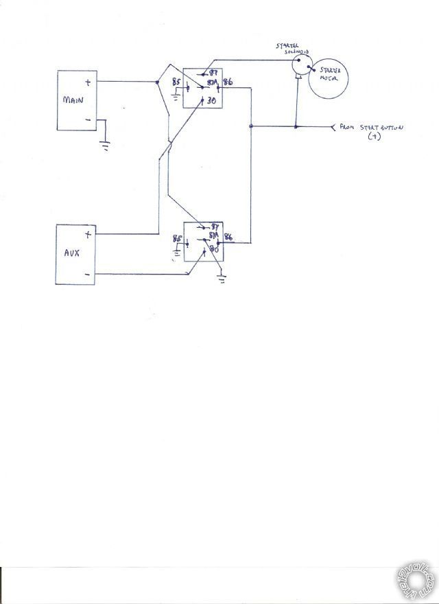 Why does he have 2 dpdt relays. I just can't seem to figure it out.. (brain shut down) I looked in the old relay box found a 4PDT 6v dc relay!!!! 6v coil but able to pass 5A/28v DC. This is just what the doctor ordered? Why can't I grasp what goes where??? 14 (6v coil) 13 12 11 10 9
Sorry I forgot about the first diagram you sent. I apologize have lots of projects on the go @ moment.
I notice now a few links off that post. ended up looking @ this diagram by WEENWhy does he have 2 dpdt relays. I just can't seem to figure it out.. (brain shut down) I looked in the old relay box found a 4PDT 6v dc relay!!!! 6v coil but able to pass 5A/28v DC. This is just what the doctor ordered? Why can't I grasp what goes where??? 14 (6v coil) 13 12 11 10 9
8 7 6 5
4 3 2 1
common pins 12,11,10,9 are N.C. to pins 4,3,2,1 consecutively and N.O. to pins 8,7,6,5 when 6v energizes coil. pins 14 and 13.How could I use this for the dual 6v, parallel/series. setup? With this relay I almost get the feeling I could run to 6v in parallel to charge both batteries while also using extra contacts to run series @ same time?If my previous posts made it sound like I knew what I was doing, LOL I'm sorry?Posted: March 25, 2012 at 9:09 PM / IP Logged
See I need to do it or discuss it to figure crap out..think I have a clue. let me know how far off I am......... 14 (6v coil) 13 12 11 10 9
14 (6v coil) 13 12 11 10 9
8 7 6 5
4 3 2 1
Pin 12 goes to "main batt" 6v +pin 4 goes to "aux batt" 6v +pin 8 is my 12v + OUT to lights/signal etc. pin 9 goes to "aux batt" neg.pin 1 goes to chassis groundpin 5 goes to "main batt" Neg.The main batt is connected to the charging system & chassis ground? The Aux batt doesn't get directly connected to chassis ground?The main batt will still go through the key switch and supply th 6v to power the coil, but you say add a indicator switch to remove this power so the batt will be parallel. No 12v will be available while the batteries are in parallel? Can't the extra terminals on this relay help somehow?Posted: March 26, 2012 at 5:02 AM / IP Logged
I'm too far gone for the relay analysis, but I'll get back to that.
As for Ween's diagram, it's the same as mine but his is a physical or wiring; mine is a circuit diagram. (Some say schematic too, bit I've seen that name applied to wiring-type diagrams...)
EXCEPT for one difference - Ween has my "I might swap the NO & NC relay contacts" version. Ween has swapped my 87 & 87s contacts, hence his "energised" reconnections are my normal or de-energised connections. You chose whichever version depending on desires - eg, normally de-energised when NOT needed (IGN off etc), or normally de-energised to save power, or normally energised to ensure good relay contacts - ie, not subject to opening when bumps exceed spring tension etc.
BTW - I draw circuit diagrams because it's easy to see HOW it works. And it's for any relay - ie, people like me that never learned the Bosch/Hella/DIN pin numbering (why bother?) don't have to decipher 86, 87, 87a etc.
Plus I have difficulty analysing "physical" diagrams - I usually have to convert then toa circuit drawing.
Sorry, you can NOT post a reply.
This topic is closed.
 Printable version
| You cannot post new topics in this forum You cannot reply to topics in this forum You cannot delete your posts in this forum You cannot edit your posts in this forum You cannot create polls in this forum You cannot vote in polls in this forum |

| Search the12volt.com |
Follow the12volt.com 
Tuesday, May 12, 2026 • Copyright © 1999-2026 the12volt.com, All Rights Reserved • Privacy Policy & Use of Cookies

Tuesday, May 12, 2026 • Copyright © 1999-2026 the12volt.com, All Rights Reserved • Privacy Policy & Use of Cookies
Disclaimer:
*All information on this site ( the12volt.com ) is provided "as is" without any warranty of any kind, either expressed or implied, including but not limited to fitness for a particular use. Any user assumes the entire risk as to the accuracy and use of this information. Please
verify all wire colors and diagrams before applying any information.
