the12volt.com spacer
icon

need input for a 24v led light


Post ReplyPost New Topic
< Prev Topic Next Topic >
tkmech21 
Member - Posts: 11
Member spacespace
Joined: April 16, 2010
Posted: March 21, 2012 at 8:16 PM / IP Logged  
My uncle is wanting me to make a premade 12v LED light work on 24v for his boat.  The light we are using is a Grote 60561 http://www.grote.com/product.php?product_number=60561, now the issue I am dealing with is I have no Idea what this light is constructed with, all the components are sealed.  I started safe and put a 1kohm resistor in and it barely lit the led, went down, and down, and I am currently using a 470ohm 1/2watt resistor.  With the 470 and 24 v The light output is really close to what it looks like with the standard 12v, but the resistor gets pretty hot.  I was thinking about trying the next ohm range down to see if I can get the led brighter,  but stepping up on a higher watt rating to hopefully run the resistor cooler.  Any ideas or suggestions would be greatly appreciated.  Thank you
Ween 
Platinum - Posts: 1,366
Platinum spacespace
Joined: August 01, 2004
Location: Illinois, United States
Posted: March 21, 2012 at 10:16 PM / IP Logged  
hi,
so the specs show 14 volts @ .2 amps...that equals a 70 ohm load, drawing 2.8 watts. it probably draws a little less current at 12V, but use the specs given. math time...... (24V - 14V)/.2A = 50 ohms.
.2A^2 * 50ohms = 2 watts ..use 2 times plus for safety factor equals minimum 4 watts. so select a 50 ohm 5 watt resistor.
now does the boat run at more than 24V nominal when the light is to be used? that will change the 24V to a higher value, which will change the resistor value (higher value).
hope this helps,
mark
oldspark 
Gold - Posts: 4,913
Gold spacespace
Joined: November 03, 2008
Location: Australia
Posted: March 22, 2012 at 1:09 AM / IP Logged  
You could use a current limiter.
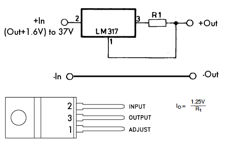
A 3-pin LM317 adjustable voltage regulator with a 1/2 Watt 5.6 Ohm resistor limits the current to 0.21A - ie, I-limit = 1.2V / R.
The 317 will dissipate (say 14V x .21A =) ~3W so the LM317T (TO-220 package; 15W) is probably best.
[ The 7.5W TO-202 LM317M also; but the small TO-39 is only 2W and therefore needs a heatsink, and the TO-3 (20W) is a PITA to mount. ]
The TO-220 package as shown in the fig below is common and easy to use - you can solder the resistor between the center pin (the 117's output) and the outer "adjust" pin.
Note that 24V input is to the outer #2 INPUT pin, and the output to the LED is taken from the other outer #1 ADJUST pin - NOT the 317's middle #3 OUTPUT pin/leg!   
It's a simple and cheap circuit ($2?) and its has its own thermal limiting and over-current protection.
It's as simple as this diagram from www.otherpower.com....
need input for a 24v led light -- posted image.
... as found on Home Built LED Lighting.
NOTE that I have just emailed otherpower.com seeking permission to use the diagram above.
Note too that any the12volt.com automated Copyright watermark may be invalid.
[ FYI: I spotted the above diagram and "just had to" use it. I was intending to link the normal & common Databook version else draw my own, but IMO the Otherpower.com's pic was just so good...
And incidentally, I tried not to get distracted, but I kept finding great info on their site... ]
You may notice the 1.25V versus 1.20V for my "I = 1.2V/R". That's a specification issue - the typical versus minimum "Reference Voltage".
The original Databooks usually use the minimum, ie 1.2V. (Hence the 120Ù "reference" resistor value for a minimum load of 10mA for a stable output.)
But that should trivial, especially when rounding to common preferred resistor values.
And the max current isn't that critical anyhow - just decide if you want a bit above the LED's spec'd 200mA or a bit below.
The LED may draw less anyhow - the programmed current limit is merely the upper limit - the circuit/LED can draw less current.
Not that I wanted to present a Design-101 class...
But, that's me!
tkmech21 
Member - Posts: 11
Member spacespace
Joined: April 16, 2010
Posted: March 22, 2012 at 6:25 AM / IP Logged  
Thanks guys for the info, I will play with it more today. I just came back in the shop and I have had the LED running on batteries since yesterday morning about 9am, it is still running with the 470 ohm resistor as i mentioned in my post. resistor is still hot, as i expected it to be. But i would feel much better going a safer route. As far as the voltage fluctuating, I am not positive but would assume the voltage will go slightly higher when under way, with alternators running. This is a 62' ocean sport fisher, when docked it is connected to shore power so voltage should be steady then.
oldspark 
Gold - Posts: 4,913
Gold spacespace
Joined: November 03, 2008
Location: Australia
Posted: March 22, 2012 at 8:37 AM / IP Logged  
If it's a 470R resistor, then the LED's 0.2A spec must be wrong - I think they mean 0.02A = 20mA. ( V=IR => .2A x 470R = 94V across the resistor, and nearly 20 Watts. 20mA means 9.6V at 0.2W. 12V across 470R means 25mA @ .3W, etc.)
But if 470R is ok, I'd suggest a 1W or maybe even 2W or 5W version as their larger size dissipates heat much better.
And you should be designing for a 14V drop - not that it makes much difference.
(A 12V system is normally ~14 to 14.5V with alternator-charging, ie, 28 - 29V in a 24V system. Note that an automotive "12V" LED or load is designed to handle 14.5V etc.)
PS - yet again, incorrect info published on manufacturer's sites - incorrect solutions from Rostra, ...., ...., simple LED specs...
Yep, devolution is evolving as predicted.
oldspark 
Gold - Posts: 4,913
Gold spacespace
Joined: November 03, 2008
Location: Australia
Posted: March 22, 2012 at 11:43 AM / IP Logged  
Copyright update:
With a big thanks to otherpower.com
Dan Fink, the Executive Director of Otherpower, has kindly responded and given permission for the use of their image in my last reply.
Alas I can't back edit my reply, hence this reply stating the good news.
Otherpower's image/diagram not only saved me concocting something similar (though probably inferior), but it was also by far the best and most suited to my intent. (And I looked at lots of images!)
And it was a double-bonus - that image led me to the otherpower.com site which impressed me greatly. For anyone else into alternative power, and batteries, etc, may I suggest a visit...
Though still as yet only a cursory glance, I am keen to peruse their site in greater detail. (What a pity it's 3:30AM here now! And with no sleep last night, I really should get to bed. Now. Else maybe soon...)
I suspect I have found another - but rare - reference site. Yay!
Yep - it's been a good day.

Sorry, you can NOT post a reply.
This topic is closed.

  Printable version Printable version Post ReplyPost New Topic
You cannot post new topics in this forum
You cannot reply to topics in this forum
You cannot delete your posts in this forum
You cannot edit your posts in this forum
You cannot create polls in this forum
You cannot vote in polls in this forum

  •  
Search the12volt.com
Follow the12volt.com Follow the12volt.com on Facebook
Friday, May 3, 2024 • Copyright © 1999-2024 the12volt.com, All Rights Reserved Privacy Policy & Use of Cookies
Disclaimer: *All information on this site ( the12volt.com ) is provided "as is" without any warranty of any kind, either expressed or implied, including but not limited to fitness for a particular use. Any user assumes the entire risk as to the accuracy and use of this information. Please verify all wire colors and diagrams before applying any information.

Secured by Sectigo
the12volt.com spacer
Support the12volt.com
Top
the12volt.com spacer