


2007 Chevrolet HHR Alarm/Remote Start Pictorial
Home /
the12volt's Install Bay /
Car Security and Convenience - Alarm/Remote Start Pictorials / 2007 Chevrolet HHR Alarm/Remote Start Pictorial ( Topic Closed)


Posted: April 29, 2012 at 3:01 PM / IP Logged
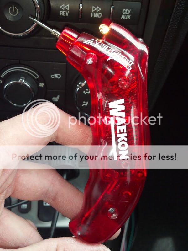 The victim
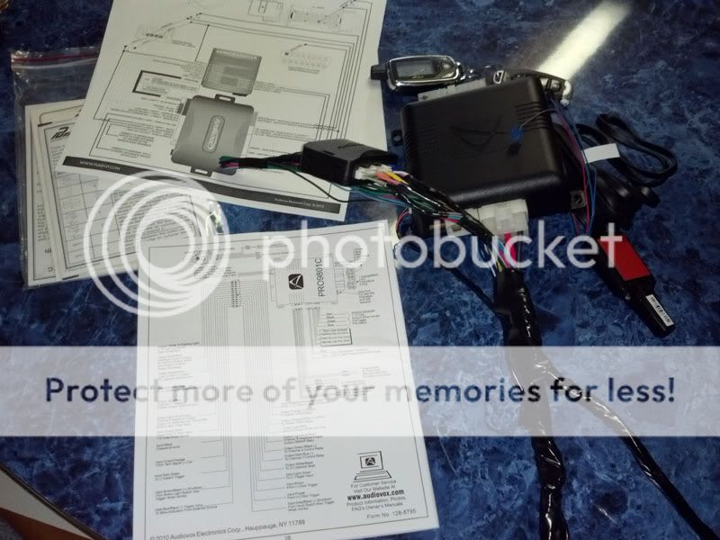
 The remote start and bypass prepped. Note the data brake signal did not work as indicated and had to be hooked up at the brake switch (not shown Light blue)
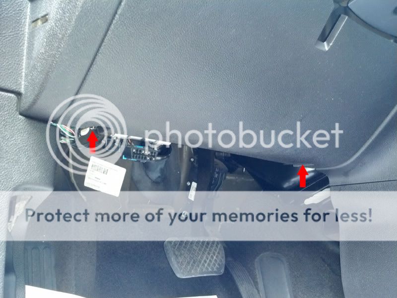
 Start under the drivers side dash and remove the two 7mm (9/32) bolts below the knee pad, and then pull the cover free.
 Next, remove the three 7mm (9/32) bolts under the steering column shroud. You need to remove the knee covers before attempting to remove this steering wheel shroud. It isn't easy to twist this cover out. Be careful!
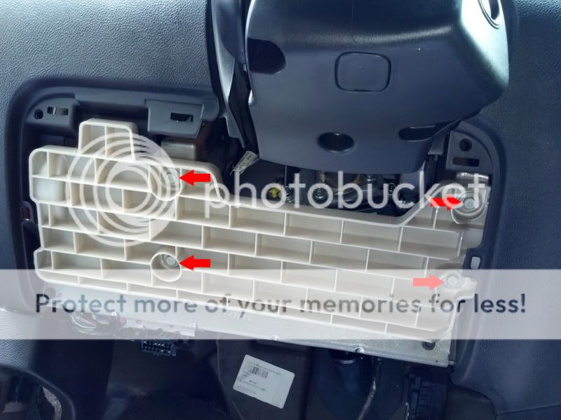
 Remove the four 10mm bolts securing the inner knee bolster to the dash. The you can carefully remove the lower steering column shroud completely.
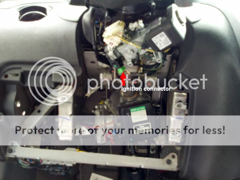
 Here is a shot of the workspace available on this side of the dash and the ignition harness/connector indicated by the red arrow can be seen.
 On the passenger side of the center console where the bcm/fusebox lies you will see 3 connectors as pictured. The large red connector is C3 and contains the positive parking lights (brown), the largest RED / black wire is the main feed for the BCM and can be used safely to power anything up to 25amps. For this unit I used a 20 amp fuse.
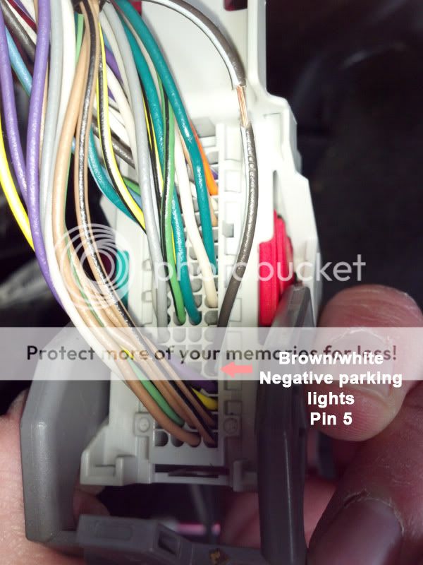
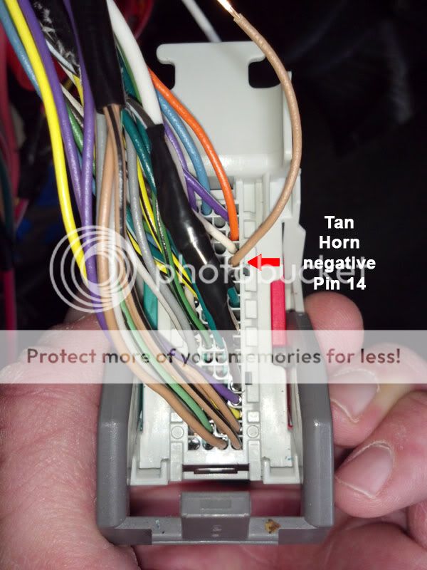
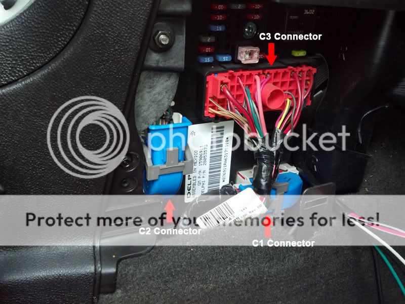 The connector on the left is C2. This contains the negative parking lights (BROWN / white pin 5), the horn wire (tan pin 14), and the security LED (green pin 11) as pictured below.
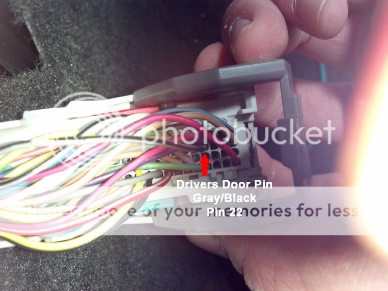
 The bottom connector is C1 and contains the Door pin wires I only needed the drivers door (gray/black pin 22). The others are in this connector and can be found easily.
 Not pictured is the hoodpin and ground. Pretty simple install, if you use a data module that does the hard work for you. As with most of these 06+ GM cars you need to plan out where your remote start brain is going to live. I made every single wire in this install longer than what it came out of the box. I have seen guys place the brain in that bcm area, or above the drivers foot well. Just be sure you plan ahead and route things cleanly.
Posted: April 30, 2012 at 10:21 AM / IP Logged
 Forgot to post the close up up the ignition connector
 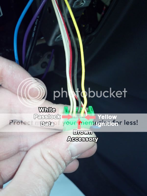 You can also see the RED / white 12v wire here. Flash-logic describes using this to power the bypass separately, but since I got power from the main BCM feed it should be plenty accurate. Basically they want to make sure the bypass is using the same reference 12v that the BCM is for the passlock wire. Do NOT power a remote start from this small wire!
  I didn't post a picture of the OBDII connector, as most of the bypasses that use this as a connection should have a pin-out listed in their instructions. On the malibu, G6, HHR, cobalt, and G5 platforms they should all be the top left #1 pin, top being the wider side of the connector, and left as viewed from the open side where you plug your scan tool in. Hope that helps!
Thanks to kreg357 for the feedback!
I didn't post a picture of the OBDII connector, as most of the bypasses that use this as a connection should have a pin-out listed in their instructions. On the malibu, G6, HHR, cobalt, and G5 platforms they should all be the top left #1 pin, top being the wider side of the connector, and left as viewed from the open side where you plug your scan tool in. Hope that helps!
Thanks to kreg357 for the feedback! 
Posted: April 30, 2012 at 10:29 AM / IP Logged


Posted: April 30, 2012 at 2:04 PM / IP Logged

Posted: May 13, 2012 at 1:16 AM / IP Logged
Posted: May 13, 2012 at 10:43 AM / IP Logged
Posted: December 06, 2013 at 11:04 PM / IP Logged
Posted: December 14, 2013 at 8:02 AM / IP Logged
 At least they fixed those issues!
Posted: April 16, 2016 at 3:04 PM / IP Logged
Posted: April 16, 2016 at 3:06 PM / IP Logged
 Printable version
| You cannot post new topics in this forum You cannot reply to topics in this forum You cannot delete your posts in this forum You cannot edit your posts in this forum You cannot create polls in this forum You cannot vote in polls in this forum |

| Search the12volt.com |
Follow the12volt.com 
Tuesday, May 12, 2026 • Copyright © 1999-2026 the12volt.com, All Rights Reserved • Privacy Policy & Use of Cookies

Tuesday, May 12, 2026 • Copyright © 1999-2026 the12volt.com, All Rights Reserved • Privacy Policy & Use of Cookies
Disclaimer:
*All information on this site ( the12volt.com ) is provided "as is" without any warranty of any kind, either expressed or implied, including but not limited to fitness for a particular use. Any user assumes the entire risk as to the accuracy and use of this information. Please
verify all wire colors and diagrams before applying any information.
