the12volt.com spacer
icon

Clarification on 87a Terminal of Relay


Post ReplyPost New Topic
< Prev Topic Next Topic >
gordyg 
Member - Posts: 11
Member spacespace
Joined: November 23, 2011
Location: British Columbia, Canada
Posted: May 02, 2012 at 11:44 AM / IP Logged  
I am installing a set of air horns on a truck and I would like to confirm a connection on the relay please. This air horn set comes with two compressors driving one trumpet each.
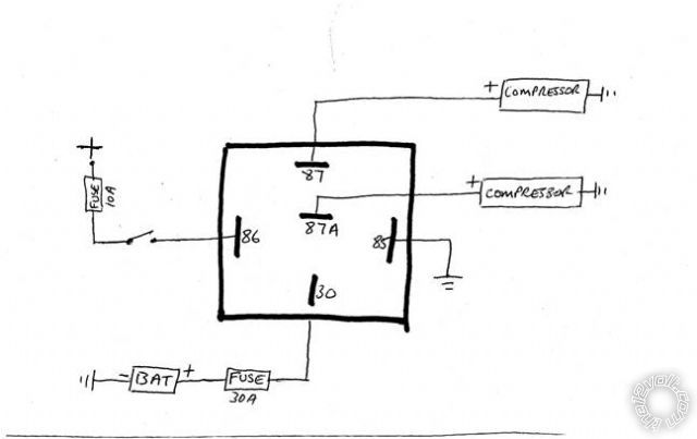
The instructions are not very detailed, but the box does show a diagram which instructs to connect the relay as I have drawn in the image below.
My concern is: will both compressors work simultaneously with one compressor connected to 87 and the other connected to 87A?
I have never used the 87a connection before and my understanding is that 87 or 87a alternate (I could be wrong). If the way they have instructed correct, I would like to know for my understanding what the advantage is of using 87a connection opposed to connecting both compressors to 87 terminal.
Could someone please clarify this for me?
Clarification on 87a Terminal of Relay -- posted image.
awdeclipse 
Copper - Posts: 285
Copper spacespace
Joined: August 05, 2007
Location: Michigan, United States
Posted: May 02, 2012 at 12:13 PM / IP Logged  
That diagram would have compressor on 87a running with the relay open (no closing of the switch on terminal 86) and the compressor on 87 running when closing the switch (turning off 87a compressor) Like you suggest, both compressors should be connected to terminal 87.
87a is the NC or normally closed terminal. It is pretty well defined in the relay section of the site.
Relay Section
Also, be sure you fuse according to wire size used.
gordyg 
Member - Posts: 11
Member spacespace
Joined: November 23, 2011
Location: British Columbia, Canada
Posted: May 02, 2012 at 12:31 PM / IP Logged  
Thanks for your clarification.
i am an idiot 
Platinum - Posts: 13,667
Platinum spaceThis member consistently provides reliable informationspace
Joined: September 21, 2006
Location: Louisiana, United States
Posted: May 02, 2012 at 7:13 PM / IP Logged  
oldspark 
Gold - Posts: 4,913
Gold spacespace
Joined: November 03, 2008
Location: Australia
Posted: May 02, 2012 at 11:20 PM / IP Logged  
Some "5-pin" relays are dual-output types with two 87 terminals.
(Warning - some relays like Hansa have them incorrectly labelled as 87 & 87a.)
howie ll 
Pot Metal - Posts: 16,466
Pot Metal spacespace
Joined: January 09, 2007
Location: United Kingdom
Posted: May 03, 2012 at 5:46 AM / IP Logged  
With two connected terminals they'd both be 87, with isolated, 87b.
oldspark 
Gold - Posts: 4,913
Gold spacespace
Joined: November 03, 2008
Location: Australia
Posted: May 03, 2012 at 6:09 AM / IP Logged  
If that's in response to my comment, I agree, but I'm just warning...
Not that it bothers me - I never paid attention to the numbering - just their housing diagram.
howie ll 
Pot Metal - Posts: 16,466
Pot Metal spacespace
Joined: January 09, 2007
Location: United Kingdom
Posted: May 03, 2012 at 6:10 AM / IP Logged  
I test them naah.
gordyg 
Member - Posts: 11
Member spacespace
Joined: November 23, 2011
Location: British Columbia, Canada
Posted: May 03, 2012 at 11:34 AM / IP Logged  
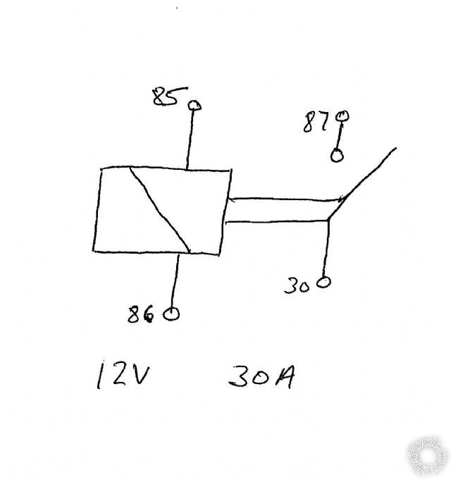
Just to add, I tested terminals 30 and 87a with an ohmeter and it is a closed connection, 87 and 30 is open. Below is an image of the drawing on the relay itself.
So if I were to connect both compressors to terminal 87 I have to make sure I am not overloading the relay.
I dont know the current draw of these compressors, trying to find this info from the ebay seller.
Clarification on 87a Terminal of Relay -- posted image.
howie ll 
Pot Metal - Posts: 16,466
Pot Metal spacespace
Joined: January 09, 2007
Location: United Kingdom
Posted: May 03, 2012 at 12:07 PM / IP Logged  
About 15 amps each your near the limit for a single relay.
A single 4 terminal relay rated at 40amps would be a better bet.
Unless of course this is the relay they gave you.
Page of 2

  Printable version Printable version Post ReplyPost New Topic
You cannot post new topics in this forum
You cannot reply to topics in this forum
You cannot delete your posts in this forum
You cannot edit your posts in this forum
You cannot create polls in this forum
You cannot vote in polls in this forum

  •  
Search the12volt.com
Follow the12volt.com Follow the12volt.com on Facebook
Tuesday, April 23, 2024 • Copyright © 1999-2024 the12volt.com, All Rights Reserved Privacy Policy & Use of Cookies
Disclaimer: *All information on this site ( the12volt.com ) is provided "as is" without any warranty of any kind, either expressed or implied, including but not limited to fitness for a particular use. Any user assumes the entire risk as to the accuracy and use of this information. Please verify all wire colors and diagrams before applying any information.

Secured by Sectigo
the12volt.com spacer
Support the12volt.com
Top
the12volt.com spacer