the12volt.com spacer
icon

having trouble finding the lock/unlock wi


Post ReplyPost New Topic
< Prev Topic Next Topic >
bad_dude 
Copper - Posts: 72
Copper spacespace
Joined: May 23, 2012
Location: California, United States
Posted: July 11, 2012 at 8:37 PM / IP Logged  
The essential info. 1990 Honda Accord LX Sedan, all stock and never had alarm installed.
I have tested all of the wires that needed to be connected to the alarm. The only one I cannot confirm to be the lock and unlock with my multimeter.
The connector as pictured below is the 2 pin gray plug wrap in blue tape together with the wire harness black loom. The wires in the plugs are BLACK/ red(unlock) and BLACK/ white(lock). To test it, I ground the black of my multimeter and put the red on the connector wire, one at a time. While the multimeter is connected, I flip and switch and looking for voltage drop to zero or close to it. Nothing really drop on either wire. At rest the constant voltage shows 5.16V, as I flip the switch in either direct, the voltage goes to 5.09V, but not even close to zero. I follow this video to do my testing.
What I did to verify my testing method was to test the plug at the actual switch itself, the 2nd picture below. The wires are GREEN / WHITE, middle is black as ground, and GREEN/ red with 2 silver dots. I test both of the green wires and the voltages go from 5.16V to zero each time I flip the switch then back to 5.16V. Now that is how it's suppose to be tested and show those results.
I wonder if the lock and unlock wires can be found else where with the same or different colors. I can google any thing to be different.
Picture 1: 2 pin gray plug wrap in blue tape under the carpet.
having trouble finding the lock/unlock wi - Last Post -- posted image.
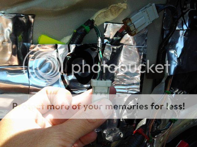
Picture 2: 3 pin plug right at the driver's door.
having trouble finding the lock/unlock wi - Last Post -- posted image.
Picture 3: The brown plug above has the BLACK/ white for door triggers and the green plug has the GREEN/ black for trunk trigger.
having trouble finding the lock/unlock wi - Last Post -- posted image.
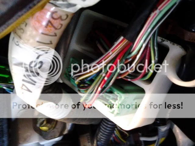
Picture 4: Big wire harness above the fuse next to the ignition harness. Are the lock or unlock wires in this one? What colors are they? Definitely not the conventional colors.
having trouble finding the lock/unlock wi - Last Post -- posted image.
I don't know what else to proceed next? I can't completely install the alarm without confirming these 2 wires. I don't really want to go back later to connect the wires. Plus I am doing priority unlock so I want to get it done now.
For priority unlock, thanks Howard: Which wire color in the door do I need to cut to isolate the front driver's door from the rest of the doors so I can connect to the relay?
Also I am collecting ideas of how to run wires from the door inside the cabin on the driver's front side as I am putting window modules in the doors. The boots seem on tight and I don't want to drill any thing. Maybe I have to take the fender off. I have read the sticky thread on this forum of that wonderful proper way to run wires through the door but my door is different.
Thanks.
kreg357 
Platinum - Posts: 7,783
Platinum spaceThis member has made a donation to the12volt.com. Click here for more info.spaceThis member has been recognized as an authority in Electrical Theory. Click here for more info.spaceThis member has been recognized as an authority in Mobile Security and Convenience. Click here for more info.spacespace
Joined: January 30, 2009
Location: Pennsylvania, United States
Posted: July 11, 2012 at 9:12 PM / IP Logged  

To test for a Type B (-) lock wire, set the DMM to +20V DC.  Connect the Red lead to +12V constant and the Black lead to the

suspect wire.  When the lock (or unlock) is pulsed, you should see the DMM go to +12V.

Note from DEI :

The station wagon uses GREEN / WHITE for lock and yellow/white for unlock. These wires are found either in the drivers door harness
or under the rear seat.

Locate the large harness in the lower below the carpet in the drivers kick panel. Near the foot rest you will notice a piece of blue tape

attached to the harness itself. Reach around to the underside of the blue tape to locate a 2 pin gray plug with the lock and unlock wires
attached to the plug.

Power Lock           BLACK/ white  (-)      lower drivers kick 

Power Unlock        BLACK/ red   (-)        lower drivers kick
 

Looks like the top picture has the correct wires...


Soldering is fun!
howie ll 
Pot Metal - Posts: 16,466
Pot Metal spacespace
Joined: January 09, 2007
Location: United Kingdom
Posted: July 12, 2012 at 1:49 AM / IP Logged  
You'll drive yourself mad using a DMM on a car of this age, go to a scrap yard and pick up a side light (10 watts) with the two leads, attach a clip to one side and ground it*, solder finish (tin) the other end, throw over the driver's door shut so the vehicle thinks all the doors are shut, make sure key isn't in the ignition, then feed the other end of the bulb wire to each in turn. If you've found the correct wire it will lock or unlock the vehicle then try the other wire.
*Or of course use a Snap-On tester with an incandescent bulb, still my number one test and probe method for most cars.
howie ll 
Pot Metal - Posts: 16,466
Pot Metal spacespace
Joined: January 09, 2007
Location: United Kingdom
Posted: July 12, 2012 at 1:54 AM / IP Logged  
I have't a clue which wire! Test, it sits on ground at rest, when you lock it will flash 12V+ for 0.8 secs. This is where my comment from above works, it's much easier to watch a momentary light flash than a meter!
You keep saying "in the door" if the controller isn't in the door, then it's at the kick panel.
It was a WHITE/ red on later models.
If you find a wire that matches at the kickwell, cut it and try lock-unlock. If the driver's door doesn't work you've found the right wire without having to go into the door.
bad_dude 
Copper - Posts: 72
Copper spacespace
Joined: May 23, 2012
Location: California, United States
Posted: July 12, 2012 at 11:02 AM / IP Logged  
The control module is in the door so I guess wires would have to be ran. I have a 6V/12V test light, would it work the same as what you described above Howard?
Thanks.
howie ll 
Pot Metal - Posts: 16,466
Pot Metal spacespace
Joined: January 09, 2007
Location: United Kingdom
Posted: July 12, 2012 at 11:10 AM / IP Logged  
Yes if it's incandescent (filament) rather than say LED.

Sorry, you can NOT post a reply.
This topic is closed.

  Printable version Printable version Post ReplyPost New Topic
You cannot post new topics in this forum
You cannot reply to topics in this forum
You cannot delete your posts in this forum
You cannot edit your posts in this forum
You cannot create polls in this forum
You cannot vote in polls in this forum

  •  
Search the12volt.com
Follow the12volt.com Follow the12volt.com on Facebook
Saturday, May 4, 2024 • Copyright © 1999-2024 the12volt.com, All Rights Reserved Privacy Policy & Use of Cookies
Disclaimer: *All information on this site ( the12volt.com ) is provided "as is" without any warranty of any kind, either expressed or implied, including but not limited to fitness for a particular use. Any user assumes the entire risk as to the accuracy and use of this information. Please verify all wire colors and diagrams before applying any information.

Secured by Sectigo
the12volt.com spacer
Support the12volt.com
Top
the12volt.com spacer