the12volt.com spacer
icon

dim bi xenon relay diagram


Post ReplyPost New Topic
< Prev Topic Next Topic >
efcase 
Member - Posts: 16
Member spacespace
Joined: September 15, 2010
Location: United States
Posted: August 29, 2012 at 4:02 AM / IP Logged  

Before i start please move if need be

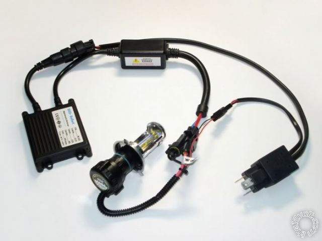
i have a set of bi xenon (h4) that id like to add relays to, it seem to be very dim on low beam and at times when high beam works i feel i have to rev the car a while to charge(?) the ballast to kick over to high beam. on my kit each ballast requires a harness unlike the single harness type that wires both lights together. heres a picture that explains what i have

[IMG]https://i46.tinypic.com/33ni16v.jpg[/IMG]

now ive searched and searched and found a few diagrams that seem like they'll work but im unsure now since i realized each ballast already has what seems like a relay, im not sure if this is to kick from low to high or to feed power.

the reason i went with this kit came down to it being a clean install.  im hoping adding a few relays will fix this and heres what i gather (to keep it clean)

#30- fused power from battery

#86-ground

#85-to high beam on stock harness

#87-to high on bulb side

#87a-to low on bulb side

Please by all means tell me where im wrong, if you can please explain what options i have. id like to wire each bulb to its own relay/relays.   

Thanks for your time

efcase 
Member - Posts: 16
Member spacespace
Joined: September 15, 2010
Location: United States
Posted: August 29, 2012 at 4:05 AM / IP Logged  

dim bi xenon relay diagram -- posted image.

efcase wrote:

Before i start please move if need be

i have a set of bi xenon (h4) that id like to add relays to, it seem to be very dim on low beam and at times when high beam works i feel i have to rev the car a while to charge(?) the ballast to kick over to high beam. on my kit each ballast requires a harness unlike the single harness type that wires both lights together. heres a picture that explains what i have

[IMG]https://i46.tinypic.com/33ni16v.jpg[/IMG]

now ive searched and searched and found a few diagrams that seem like they'll work but im unsure now since i realized each ballast already has what seems like a relay, im not sure if this is to kick from low to high or to feed power.

the reason i went with this kit came down to it being a clean install.  im hoping adding a few relays will fix this and heres what i gather (to keep it clean)

#30- fused power from battery

#86-ground

#85-to high beam on stock harness

#87-to high on bulb side

#87a-to low on bulb side

Please by all means tell me where im wrong, if you can please explain what options i have. id like to wire each bulb to its own relay/relays.   

Thanks for your time

oldspark 
Gold - Posts: 4,913
Gold spacespace
Joined: November 03, 2008
Location: Australia
Posted: August 29, 2012 at 4:40 AM / IP Logged  
Is your battery faulty, or alternator faulty?
Needing to rev indicates either or both the above. Else maybe an older alternator (with external regulator).
What is the battery voltage, and alternator voltage, at idle and revs with & without lights on?
efcase 
Member - Posts: 16
Member spacespace
Joined: September 15, 2010
Location: United States
Posted: August 29, 2012 at 5:01 PM / IP Logged  

oldspark wrote:
Is your battery faulty, or alternator faulty?
Needing to rev indicates either or both the above. Else maybe an older alternator (with external regulator).
What is the battery voltage, and alternator voltage, at idle and revs with & without lights on?

its a 97 honda delsol,since i just rebuilt the motor i replaced everything to go with it. battery, starter and alternator is less the a year old and is about 12 off with a multi meter if i remember correctly and my cap states 13.7-14.5 while running. system works great no flat spots either.  i had them working but  noticed since i unpluged them to fix something else the 1st time i pluged them in i had to leave them on low beam while the car idle'd for a few minutes and then highbeam worked, now high beam kicks on one light and not the other. unless i take a long ride then it fires back up if i flick between them fast

i have the same kit on my bike and notice on my motor cycle if not ran for a few days i have to hold rev for a few minutes or take it for a little ride in order for high beam to work also. i know bikes have poor wiring and or no alternator.  i should have some sort of relay or thicker gauge harness. i hate adding bigger fuses but the hid guy told me go to a #20, i did go from 10 to 15 and no change

oldspark 
Gold - Posts: 4,913
Gold spacespace
Joined: November 03, 2008
Location: Australia
Posted: August 30, 2012 at 2:44 AM / IP Logged  
Bikes do have alternators - except for "total loss" racing bikes etc.
It sounds like it's either a crap system, else the wiring gauge is too small.
If the HID guy told you to use a 20A fuse and the wiring (and relay) isn't rated for it, then he's a fracken idiot.
Ensure the power and ground cables are of sufficient gauge.
A voltmeter should indicate the voltage drops they are causing.
efcase 
Member - Posts: 16
Member spacespace
Joined: September 15, 2010
Location: United States
Posted: August 30, 2012 at 3:58 PM / IP Logged  
i wouldnt doubt it since ive been having these problems with both kits..  i was kinda under the impression that since its a older car and the wiring is on the thin side, looks to be 22ga or smaller id have to add a relay anyways.  i was adding a thicker ga harness with a ceramic socket. Yet on my peterbilt ive had a few problems with them taking to much juice from the thinner wire and melting. im not 100% sure where to start.. 12volt was great with my alarm install so i didnt think twice to ask for some help here. i also appreciate your help very much
oldspark 
Gold - Posts: 4,913
Gold spacespace
Joined: November 03, 2008
Location: Australia
Posted: August 30, 2012 at 4:28 PM / IP Logged  
Thinner wires actually means less juice - they are higher resistance so less current (except for "constant power" etc SMPS powered stuff like HIDs & amps should have).
But thinner wires get hot and melt - too much current (Amps) thru to thin a gauge.
Increasing gauge reduces resistance, hence less heat and a lower voltage drop.
PS - Peter-fixes are usually good.
Regards,
Peter the oldspark.
efcase 
Member - Posts: 16
Member spacespace
Joined: September 15, 2010
Location: United States
Posted: August 31, 2012 at 9:47 PM / IP Logged  

so your saying? or am i assuming your saying adding a thicker wire would help this problem some?

i was thinking a thicker gauge wire with a relay and the old tired oem harness to trigger the high and low beams. im just not sure how id wire each headlight (2) for high and low to work..  i came up with this idea since the relay would draw it power right from the battery.

oldspark 
Gold - Posts: 4,913
Gold spacespace
Joined: November 03, 2008
Location: Australia
Posted: September 01, 2012 at 10:45 AM / IP Logged  
Your kit has a ballast which should mean voltage drops don't matter (ie, they should be SMPS). But apparently some ballasts aren't that good. (As to AC vs DC ballasts - AC doesn't flicker but DC does (that should be crap), and only one side heats up for DC - now that is crap!).
I fit headlight relays to my vehicles and I often recommend others do the same if they want better lighting.
I use the OEM harness to trigger the relays.
I use a separate SPST relay for hi & low.
I use heavy bulb power & ground cable in the usual set up - ie, self-resetting circuit breakers else fuses (one for hi, one for low) as close to the battery as possible, and the relays where convenient along the cable that takes the shortest practical route to the bulbs. I usually run the ground both to a local chassis/body eyelet/bolt connection, AND back to the battery- (else engine or convenient point).
Hence the relays and bulbs are an add-on system. It involves merely a reconnection of the standard headlight sockets (ie, from bulbs to relay coils; hence taking the strain off the OEM harness and beam switches)) and cable & relays & bulb sockets & breakers/fuses of your choice.   
Though for normal QH & other bulbs the power could be taken from the alternator output (for max voltage with the engine running), if I have a fat cable from the alternator to the battery I may not worry about that. (I have done the Big-3, ie fatter than normal ground cables from battery- to chassis/body and engine or alternator, and heavy alternator to battery (or fuse box etc with heavy cable from battery to fusebox).
I aim for voltage drops less than 0.5V including ground - ie, the bulb voltage is no less than the alternator/battery voltage minus 0.5V.
Some consider it acceptable to have up to a 3V voltage drop. (IMO that is far from acceptable for QH bulbs.)

Sorry, you can NOT post a reply.
This topic is closed.

  Printable version Printable version Post ReplyPost New Topic
You cannot post new topics in this forum
You cannot reply to topics in this forum
You cannot delete your posts in this forum
You cannot edit your posts in this forum
You cannot create polls in this forum
You cannot vote in polls in this forum

  •  
Search the12volt.com
Follow the12volt.com Follow the12volt.com on Facebook
Saturday, April 20, 2024 • Copyright © 1999-2024 the12volt.com, All Rights Reserved Privacy Policy & Use of Cookies
Disclaimer: *All information on this site ( the12volt.com ) is provided "as is" without any warranty of any kind, either expressed or implied, including but not limited to fitness for a particular use. Any user assumes the entire risk as to the accuracy and use of this information. Please verify all wire colors and diagrams before applying any information.

Secured by Sectigo
the12volt.com spacer
Support the12volt.com
Top
the12volt.com spacer