the12volt.com spacer
icon

confused about which relay to use


Post ReplyPost New Topic
< Prev Topic Next Topic >
korrupt3dazn 
Member - Posts: 11
Member spacespace
Joined: November 15, 2012
Location: Connecticut, United States
Posted: November 15, 2012 at 10:12 AM / IP Logged  

Hi All,

I was wondering if someone could help me accomplish this project.

I want to send video to my navigation screen in my car. So I can up with an idea but not to sure how to complete it.

So when the car goes into reverse the navigation the reverse lights comes on and sends that 12volt to the Navi unit which then switches what ever is on the screen to the camera's input.

My thought was I supply navi unit with my own 12 volt source tricking the navi into thinking that im in reverse. Then install a toggle that I can switch the video switch. The reason I would want the relay is so that when I do go into reverse it can temporalily kill the my 12 volt source and supply its own. Then when Im out of reverse it restores my 12volt source?

lurch228 
Silver - Posts: 1,338
Silver spacespace
Joined: August 08, 2012
Posted: November 15, 2012 at 10:17 AM / IP Logged  
You would wire a 5 pin relay as follows. 30 to NAV, 87a your 12v, 87&86 reverse 12v, 85 ground.
korrupt3dazn 
Member - Posts: 11
Member spacespace
Joined: November 15, 2012
Location: Connecticut, United States
Posted: November 15, 2012 at 10:27 AM / IP Logged  
Great! thanks. I tried looking at the relay diagrams and wiki relay info and just got even more lost.
lurch228 
Silver - Posts: 1,338
Silver spacespace
Joined: August 08, 2012
Posted: November 15, 2012 at 1:24 PM / IP Logged  
Relays (Bosch Type) Are 87a always connected to 30 non-energized, 87 to 30 energized, coil 86 (+), 85 (-). When wired so that 30 is the output you can have 2 sources, when wired so 30 is the input you can have 2 outputs. When you are using the relay to have 2 sources to 1 output for your needs you jump the power from the switched secondary source to energize the relay coil. So the Reverse will overide the video source power. But you will still need to figure how and what you are going use to switch the video source with the power.
korrupt3dazn 
Member - Posts: 11
Member spacespace
Joined: November 15, 2012
Location: Connecticut, United States
Posted: November 27, 2012 at 12:02 AM / IP Logged  
So I did some reading on the forums:
https://www.the12volt.com/relays/relays.asp
I then had this Idea pop up while preparing for bed and figure I had to type and draw it out before I forget it the next day.
What do you guys think?
Figure A
I needed to tell the Navigation that it is in reverse. The Navi thinks its in reverse when it detects 12 volt.
I set my 12 alternative 12volt source on PIN 87a since it is always connected when relay is not energized being as it is always connected the Navi will always think it is on so I will install a Toggle switch so that I can choose when to turn on my 12 volt source.
Next hurdle was I needed the reverse light to over ride my 12 volt source. so I wired PIN 87 and 86 to the reverse lights. So when I actually do go into reverse the lights will energize the coil causing the Arm to jump from PIN 87a to 87.
Figure B
So now I need to tell the Navi what video source to use. So a RCA connector has 2 wires inside one for ground and one for the signal.
So I wired pin 30 to the video input the Navi then DVD player's input to 87a and the Reverse camera to 87.
I connected 86 to the reverse lights so that when my car goes into reverse itll energize the coil which will disconnect the arm from 87a ( DVD PLayer ) and connect to 87 ( Reverse Camera ). Then when I shift back to another gear the coil will be de-energized and restore my DVD players video inputconfused about which relay to use -- posted image.
lurch228 
Silver - Posts: 1,338
Silver spacespace
Joined: August 08, 2012
Posted: November 27, 2012 at 4:23 AM / IP Logged  
If your going to use regular relays for the video you will need to use 2 relays to switch both the ground and video together. The one caveat is your video sources quality may suffer with non sheilded relays, they make video selectors that are designed to do what you want but they can be expensive and hard to find. At a minimum I would recomend a old video game RF adapter modified for your use which has the filters and noise traps built in. But it will require you to open it up and modify the circuit to bypass the RF conversion to channel 3 output so it passes the rca signal straight thru no conversion. It can be done as I have read posts to that fact in the past but have never done it myself.
korrupt3dazn 
Member - Posts: 11
Member spacespace
Joined: November 15, 2012
Location: Connecticut, United States
Posted: November 27, 2012 at 6:08 AM / IP Logged  
ok great. I will go pick these relays of today and try and assemble them. Thanks for the response :-) I still learning and this is all new to me so I think I did pretty good haha.
korrupt3dazn 
Member - Posts: 11
Member spacespace
Joined: November 15, 2012
Location: Connecticut, United States
Posted: November 27, 2012 at 8:50 AM / IP Logged  
confused about which relay to use -- posted image.
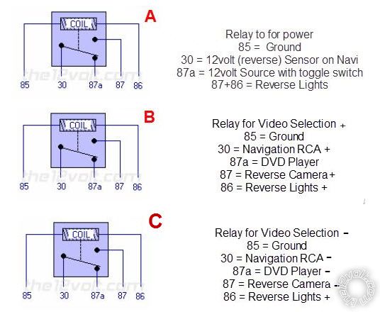
Here is an updated one. I have a good feeling about this guys that it will work!
lurch228 
Silver - Posts: 1,338
Silver spacespace
Joined: August 08, 2012
Posted: November 27, 2012 at 2:20 PM / IP Logged  
For the concern of saving space if you can find them use micro relays as you don't have a high amp demand for what you are doing.
And you can use one relay for the video control of both the (+), (-) legs on each side. So as you can see in the below pic. You will have from left to right 2 banks of 3 connections plus the 2 coil connections on the right. Think of it as 2 relays in one but only one control coil switching both banks.
For example from let to right top 1 bank would be 87, 30, 87a,, 86 (+)
And bank 2 lower row of left to right pins will be 87, 30, 87a,, 85 (-)
confused about which relay to use -- posted image.
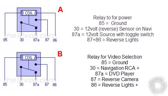
Relay diagram from relay link below.
DPDT Relay
korrupt3dazn 
Member - Posts: 11
Member spacespace
Joined: November 15, 2012
Location: Connecticut, United States
Posted: November 29, 2012 at 9:43 PM / IP Logged  
I finished up building it! Thank lurch228!!!! Couldn't have done it without your guidance! I tested it out and it works as planned. Thankfully I used the DPDT relay instead of using 3 5PIN SPDT. The box would've been huge.
confused about which relay to use -- posted image.
Page of 2

  Printable version Printable version Post ReplyPost New Topic
You cannot post new topics in this forum
You cannot reply to topics in this forum
You cannot delete your posts in this forum
You cannot edit your posts in this forum
You cannot create polls in this forum
You cannot vote in polls in this forum

  •  
Search the12volt.com
Follow the12volt.com Follow the12volt.com on Facebook
Thursday, March 28, 2024 • Copyright © 1999-2024 the12volt.com, All Rights Reserved Privacy Policy & Use of Cookies
Disclaimer: *All information on this site ( the12volt.com ) is provided "as is" without any warranty of any kind, either expressed or implied, including but not limited to fitness for a particular use. Any user assumes the entire risk as to the accuracy and use of this information. Please verify all wire colors and diagrams before applying any information.

Secured by Sectigo
the12volt.com spacer
Support the12volt.com
Top
the12volt.com spacer