the12volt.com spacer
icon

viper 5704 comm issue


Post ReplyPost New Topic
< Prev Topic Next Topic >
lurch228 
Silver - Posts: 1,338
Silver spacespace
Joined: August 08, 2012
Posted: December 03, 2012 at 10:17 AM / IP Logged  
KPierson wrote:
But if he connected the system directly to the battery that would rule out a bad in car ground. If the poor ground was a chassis ground and he chassis grounded the system I could see there being a problem. But, if he connected the system directly to the battery a poor chassis ground shouldn't affect anything.
This would be completely true if the battery wasn't still connected to the rest of the car's electrical system where the problem of intereference is coming from. That's why when he tested the comm. with a spare battery connected to just the viper it worked fine with the motor running. Which leads back to a lack of ground, and he now says that he has no straps to the engine on a EFI setup.
tylerwayne 
Member - Posts: 34
Member spacespace
Joined: June 05, 2010
Location: Texas, United States
Posted: December 03, 2012 at 10:42 AM / IP Logged  
lurch228 wrote:
KPierson wrote:
But if he connected the system directly to the battery that would rule out a bad in car ground. If the poor ground was a chassis ground and he chassis grounded the system I could see there being a problem. But, if he connected the system directly to the battery a poor chassis ground shouldn't affect anything.
This would be completely true if the battery wasn't still connected to the rest of the car's electrical system where the problem of intereference is coming from. That's why when he tested the comm. with a spare battery connected to just the viper it worked fine with the motor running. Which leads back to a lack of ground, and he now says that he has no straps to the engine on a EFI setup.
To clarify, The alternator ground is created from the mounting bolt, not a strap.
I do have the following grounds:
Battery to frame (trunk mounted)
Engine to frame
Main harness to frame
EFI harness to engine (intake)
I will test these ground for resistance later today.
howie ll 
Pot Metal - Posts: 16,466
Pot Metal spacespace
Joined: January 09, 2007
Location: United Kingdom
Posted: December 03, 2012 at 11:38 AM / IP Logged  
I'm still betting on the injector wiring.
Euro GMs (Vauxhall and Opel) had years of problems with the injector and coil pack looms. And that was OEM, even though the Bosch based system was identical to that used by VW.
In fact on both Vauxhall Astra (Saturn Astra) and Golf Mk IV there have been idling problems with R/S tach wires being connected to an injector wire even though the R/S units are supposedly high impedance buffered.
tylerwayne 
Member - Posts: 34
Member spacespace
Joined: June 05, 2010
Location: Texas, United States
Posted: December 03, 2012 at 12:38 PM / IP Logged  
howie ll wrote:
I'm still betting on the injector wiring.
Euro GMs (Vauxhall and Opel) had years of problems with the injector and coil pack looms. And that was OEM, even though the Bosch based system was identical to that used by VW.
In fact on both Vauxhall Astra (Saturn Astra) and Golf Mk IV there have been idling problems with R/S tach wires being connected to an injector wire even though the R/S units are supposedly high impedance buffered.
So if this was true, what would be the remedy? Could I use a diode to isolate the circuit?
I have a relay pack to supply the EFI harness and I am going to narrow down what each one is supplying and where the continuity to ground is coming from.
tylerwayne 
Member - Posts: 34
Member spacespace
Joined: June 05, 2010
Location: Texas, United States
Posted: December 03, 2012 at 5:53 PM / IP Logged  
OK here is an update:
The picture below shows the relay pack with the ignition switch feeding the 85 pin, orange wire. the wires on the right are the output wires(87). Two of the 87 wires have continuity to ground, to the O2 sensors and fuel pump. I disconnected the O2 sensor and bypassed the relay for the fuel pump. Supplied power straight from battery, still no comm.
viper 5704 comm issue - Page 7 -- posted image.
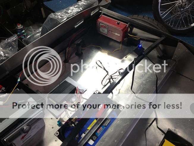
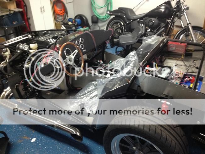
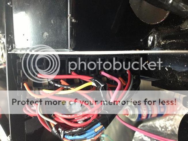
The continuity to ground from the IGN post while IGN off is coming form the relay pack. 85 is ground and 86 is signal from IGN post, about 88Ohms X 3 in series gets you to the 29~ Ohms I am getting at the IGN switch.   
At the battery I am getting 14.20vdc while running.
All grounds, frame to battery, frame to engine, EFI harness to engine, main harness to frame are <0.5ohms
I do not think the continuity to ground from IGN post is causing the no comm issue. If that were the case, then a simple dash light wired from the IGN post to ground would cause a no comm issue while running.
Photos:
viper 5704 comm issue - Page 7 -- posted image.
tylerwayne 
Member - Posts: 34
Member spacespace
Joined: June 05, 2010
Location: Texas, United States
Posted: December 03, 2012 at 6:09 PM / IP Logged  
Additional information, as my mind was trying to determine a way to have the car running without the EFI harness as part of the circuit...
Eureka...So the EFI Ron Morris harness has a direct connect to the battery post, along with the normal lead clamp 2 gauge battery wire.
I started the car, disconnected the main battery wire (2 gauge), no comm. disconnected the main battery wire and EFI harness.....I get comm with remote.
AKA I was running the car with the alternator provides the current and battery outside the circuit. However that may show that the EFI harness is having an affect. I cannot try to test the other way though (main battery cable connected and EFI disconnected since the EFI harness pulls power from it). The only way to eliminated the main harness from error is to run the EFI harness on separate battery and try to comm while engine running and main harness hooked up to car battery.
howie ll 
Pot Metal - Posts: 16,466
Pot Metal spacespace
Joined: January 09, 2007
Location: United Kingdom
Posted: December 04, 2012 at 1:03 AM / IP Logged  
Right so I was on the right track with the EFI, any way to physically separate the battery leads from the rest?
howie ll 
Pot Metal - Posts: 16,466
Pot Metal spacespace
Joined: January 09, 2007
Location: United Kingdom
Posted: December 04, 2012 at 1:07 AM / IP Logged  
I would also like to point out that this isn't a grounding issue, it's an interference issue, suppression interference, a lost art for installers with the advent of Phillips IAC circuitry in the mid 70s for suppressing noise on FM circuits.
Think shielding rather than grounding.
tylerwayne 
Member - Posts: 34
Member spacespace
Joined: June 05, 2010
Location: Texas, United States
Posted: December 04, 2012 at 8:09 AM / IP Logged  
howie ll wrote:
I would also like to point out that this isn't a grounding issue, it's an interference issue, suppression interference, a lost art for installers with the advent of Phillips IAC circuitry in the mid 70s for suppressing noise on FM circuits.
Think shielding rather than grounding.
Would the interference effect the circuit? I tested the comm with the viper connected directly to a spare battery outside vehicle circuit. comm worked fine while vehicle was running.
howie ll 
Pot Metal - Posts: 16,466
Pot Metal spacespace
Joined: January 09, 2007
Location: United Kingdom
Posted: December 04, 2012 at 10:27 AM / IP Logged  
That points to inductance rather than radiation.
Lotus Europa, the Europa bit being the engine out of a Renault 16, mid 70s. Fiberglass body.
Aluminium foil glued to underside of hood.
Grounding bonds to hood to engine block to bodywork.
3mfd. cap on alternator.
1mfd. cap on coil.
Exhaust pipe bonded back to engine.
Page of 9

  Printable version Printable version Post ReplyPost New Topic
You cannot post new topics in this forum
You cannot reply to topics in this forum
You cannot delete your posts in this forum
You cannot edit your posts in this forum
You cannot create polls in this forum
You cannot vote in polls in this forum

  •  
Search the12volt.com
Follow the12volt.com Follow the12volt.com on Facebook
Friday, March 29, 2024 • Copyright © 1999-2024 the12volt.com, All Rights Reserved Privacy Policy & Use of Cookies
Disclaimer: *All information on this site ( the12volt.com ) is provided "as is" without any warranty of any kind, either expressed or implied, including but not limited to fitness for a particular use. Any user assumes the entire risk as to the accuracy and use of this information. Please verify all wire colors and diagrams before applying any information.

Secured by Sectigo
the12volt.com spacer
Support the12volt.com
Top
the12volt.com spacer