the12volt.com spacer
icon

hi/low beam relay problem w/ picture


Post ReplyPost New Topic
< Prev Topic Next Topic >
fc3s522 
Member - Posts: 1
Member spacespace
Joined: December 28, 2012
Location: California, United States
Posted: December 28, 2012 at 3:57 PM / IP Logged  
Trying to install aftermarket lights on my car. The middle two lights are supposed to be on for low beam, and all four for high beams.
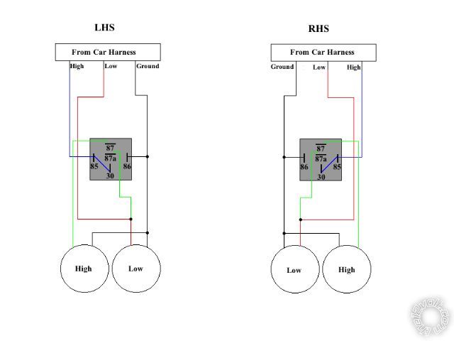
Unfortunately, I have a limited electrical experience. Presently, all four light up when switched to both high and low. I have made a wiring schematic to show how I have it wired (shown below) to help with diagnosis.
I believe it has to do with the low beam wire sending power back to the relay. Can i solve this with a diode?
-Sean
hi/low beam relay problem w/ picture - Last Post -- posted image.
KPierson 
Platinum - Posts: 3,527
Platinum spaceThis member consistently provides reliable informationspace
Joined: April 14, 2005
Location: Ohio, United States
Posted: December 28, 2012 at 5:10 PM / IP Logged  
The problem is the way the relay is installed - a diode won't help you.
What's going on is when you turn on your high beams you are energizing the relay (connecting Pin 30 to Pin 87) which in turn is powering your low beams.
You need to keep the high beam and low beam circuits isolated - use a separate relay for high beam and low beam.
Kevin Pierson
turboled 
Member - Posts: 22
Member spacespace
Joined: December 29, 2006
Posted: December 30, 2012 at 11:32 AM / IP Logged  
I believe you want the low beams to be on with either the Low or High beam input, and the high beams to be on only with the High beam input.
You cannot use the high beam input to send power to the low beams, you need to use another fused power source from the battery and isolate the circuits (break the connection between pins 30 and 85)
You can use a diode between the high beam input and low beam, you don't even need a relay in that case. But the diode drops the voltage a bit (around 0.7 v) that will reduce power to your low beam. Not something you want.
Also take note to wire the relay with the positive side on pin 86 and ground on pin 85. If there is an internal diode in the relay, it will blow otherwise.
turboled 
Member - Posts: 22
Member spacespace
Joined: December 29, 2006
Posted: December 30, 2012 at 7:12 PM / IP Logged  
After second though, your circuit should work with one minor modification; connect the low beam to pin 87, not 87a. You should leave pin 87a disconnected. This will cause both the low and high beams to receive power once the relay is closed. When the relay is open, no current will flow through the relay and everything will work normally.
KPierson 
Platinum - Posts: 3,527
Platinum spaceThis member consistently provides reliable informationspace
Joined: April 14, 2005
Location: Ohio, United States
Posted: December 31, 2012 at 8:08 AM / IP Logged  
You need to be careful about overloading circuits if you are using the OEM light feed to power additional loads. It is very possible that adding a second headlight will cause your headlight fuse to blow. The additional lights should be powered through a fused source connected to the battery.
Kevin Pierson
oldspark 
Gold - Posts: 4,913
Gold spacespace
Joined: November 03, 2008
Location: Australia
Posted: January 01, 2013 at 4:53 AM / IP Logged  
The simplest is to use one SPST relay for hibeam and one for low beam.
They can have their own supply from the battery (each via a self-resetting circuit breaker) but be triggered from the original headlight sockets.
Usually it's the outer 2 beams that are on for low beam (that's the usual regulation - not inner beams).
And for low beam on all the time (even with high beams - ie, the lows are dedicated low with np high-beam filament), the low beam relay is triggered by the "beam" power - ie, the wire that goes to the dipper switch. The dipper than acts as a simple on/off for the high beam (not a changeover between hi & lo beams).

Sorry, you can NOT post a reply.
This topic is closed.

  Printable version Printable version Post ReplyPost New Topic
You cannot post new topics in this forum
You cannot reply to topics in this forum
You cannot delete your posts in this forum
You cannot edit your posts in this forum
You cannot create polls in this forum
You cannot vote in polls in this forum

  •  
Search the12volt.com
Follow the12volt.com Follow the12volt.com on Facebook
Monday, May 6, 2024 • Copyright © 1999-2024 the12volt.com, All Rights Reserved Privacy Policy & Use of Cookies
Disclaimer: *All information on this site ( the12volt.com ) is provided "as is" without any warranty of any kind, either expressed or implied, including but not limited to fitness for a particular use. Any user assumes the entire risk as to the accuracy and use of this information. Please verify all wire colors and diagrams before applying any information.

Secured by Sectigo
the12volt.com spacer
Support the12volt.com
Top
the12volt.com spacer