Yep - bingo!
I did have a diagram that matches your description (probably in my still unrecovered
crashed data) but I reckon the 2nd pic on Scott Stites'
sm_2010_3phase is perfect.
Phase 1, 2, & 3 represent off, park, & beam respectively.
You'd need to add:
- power supply filtering & protection for the 4017 itself (resistor, capacitor, and preferably a 12-14V zener diode to clamp below 15V);
- switch de-bounce circuity (probably just a resistor & capacitor);
- output tranny's or MOSFETs which could ground the coils (#85) of raw +12V powered relay coils (#86 to raw +12V; not from the "regulated" 4017 supply).
Then there may be other additions like spike protection diodes across each coil, and maybe input protection diodes...
And a POR (Power-on Reset) to ensure it powers up with lights off.
And yes, 2 diodes to "OR" or join the #1 & #2 outputs to the parker transistor/FET else relay.
One suggestion - design the relays so that you can manually energise them on in case of circuit failure - ie, reconnect #85 from the circuit to GND. (That's assuming you ground-switch the relays.)
That ability is always good to have anyhow. I once used it when the power lead to my light switch got pulled off (and the HU was in the way...)
Of course, bridging or joining the #30 & #87 pins or wires also works and is the solution for a failed relay (but we all carry a spare relay don't we?).
And FYI re the 4017...
It needs its Clock Enable to be whatever for counting - ah, I see it needs to be GND from Scott's diagram.
The 4017 resets on a +ve going pulse to its Reset pin.
Hence, using the output
0, 1, 2, ... 8, 9 nomenclature or convention, a "divide by n" counter has output #n connected to the Reset pin. Hence for your divide by 3, output 3 goes to Reset as per Scott's diagram.
Hence with POR, initially #0 is on. (But that is NC = not connected.)
First pulse
clocks to #1, hence parkers on.
Second pulse
clocks to #2, hence beam on, and - via the diode - parkers on (with the other diode preventing $2 backfeeding into #1).
Third pulse
clocks to #3, hence changing #3 from 0 (off) to 1 (on, or 12V etc) which is a +ve going pulse hence resetting the 4017 back to #0 and lights off.
Download a (good) 4017 datasheet and you'll see an excellent timing diagram, though I suggest a ruler & pencil to draw light vertical lines down from the mid-point of the clock edges (slopes) on certain key clock signals to graphically understand what I described above.
And since you are now a 4017 expert, you too will probably use the accepted digital convention where the "first output" is output #0. (Just as we do for our
centuries and baby years.)
You might cross some that label the 4017's first output as #1 (hence #1 - #10 instead of #0 - #9) and that can really confuse things - including my "n to Reset" for a div-n counter.
And of course you know that
output #n is not the same as pin #n. (And PICAXE "legs" and pins has nothing to do with this thread!)
Reread this reply if it's confusing. My expression may not be good, but as a building block, the 4017's operation is quite simple. (It's the powering and interface crap that requires know-how.)
Now if I could find the "complete" diagram I know I had...
PS - I see I missed your last reply, but hopefully we concur, and I may have provided the extra automotive electrical considerations.


 I see the reset logic on that IC too, so that is the ticket to my conundrum.
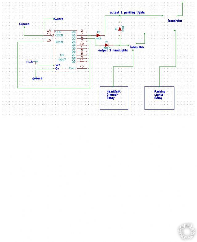
 Printable version


