Are you a typical noob? Blood oath - it's a good application!
Are you being a typical noob wanting a cheaper than an expensive commercial offering? That's not noob; that IMO is due-diligence, else the way I typically do things (with opportunity costs and other factors taken into account as applicable to the circumstance).
Are you a typical noob and over-thinking things? I don't know, but I know you're making me think (I work from "circuit" type diagrams, not wiring types)... LOL!
Firstly, THANKS for the extra info re your eventual intent (uPC etc). That makes things easier! (I think!?)
I was going to say that the relay may not be necessary, and is probably in the wrong place if it is (I'd worry about the supply capability of the Reverse switch/circuit).
But now, with a view to FINAL uPC control...
We will use a relay or relays as appropriate with a view to switches-now being replaced by a uPC etc later.
Hence maybe fit relay-coil spike protection diodes now, and maybe design for uPC switching levels. The latter might be Open-Collector especially if a 5V tablet or other
power supplied device.
How's that sound?
And any info/comment on the OC (Open Collector) switching?
Mind you, if the camera (or other devices?) cannot be GND switched (maybe because of hard or convenient chassis grounding, or other "
don't break GND" considerations) then relays will be needed anyhow, unless the uPC can switch enough +12V current to them... (I dislike the thought of three relays
merely for the cameras, but that can be deferred till later with the 3-way switch used for now...)
BTW - I see the mirror as requiring a relay so that is not an issue.
But hence an additional consideration... or two (3, 4, ...?)
Do you want this circuit disabled when IGN (or ACC) is off? IE - to prevent a flat battery.
If not, maybe a timer circuit to turn all off after some period (maybe with a manual independent bypass - ie, no IGN key required)? (Later that can be uPC controlled.)
And a point in favor of relays for the cameras...
Some cameras require "clean" DC power. Hence powered direct from the battery (via fuses!). Hence relays that connect the cameras to the battery despite the relay control signal maybe being from a
dirty IGN or ACC supply.
Plus, to convert a relay from a typical +12V switching
control signal to GND or OC control merely requires connection of its coil from GND to +12V. By convention, that means reconnecting #86 to +12V & reconnecting the #85 GND to the GND/OC switching wire.
And that matters when "reverse biased" protection diodes are fitted across the relay's coils(s).
Anyhow, that's a good excuse for me to stop here (and disguise the fact that I'm far from any thinking capability ATM).
And I'll reserve the right to realise anything stupid I wrote above and embarrass myself later. (Caveat: That does NOT preclude anyone else having that honor.)


 Topic Closed)


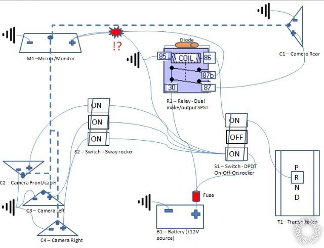 I think using a rotatory switch might be better but I like low profile flat/round toggles, advantage on one vs other? Part2 is really a later decision but Id like to setup Part1 properly, hence using a relay. Part2 is a concept in discussion to see if it is feasible. Im open to any opinions and inputs for improvements on a better way to do this. It would also be nice to automate the switching as much as possible but I cant figure that one out (left/right turn signal??). My initial setup includes a touch screen carputer setup (this is more of my realm) and use USB cams so I can use a software to stitch them together like Infintis around car view, but the cost of a proper setup is prohibitive. I would like to do this under a reasonable cost <$150-200.
Questions:
-If I remove relay (R1) and power the mirror (M1) and reverse camera (C1) directly off switch1 (S1 ON1-up), would this also indirectly power on swtich2 (S2) source?
-Am I being a typical newbie and over thinking/doing things?
I think using a rotatory switch might be better but I like low profile flat/round toggles, advantage on one vs other? Part2 is really a later decision but Id like to setup Part1 properly, hence using a relay. Part2 is a concept in discussion to see if it is feasible. Im open to any opinions and inputs for improvements on a better way to do this. It would also be nice to automate the switching as much as possible but I cant figure that one out (left/right turn signal??). My initial setup includes a touch screen carputer setup (this is more of my realm) and use USB cams so I can use a software to stitch them together like Infintis around car view, but the cost of a proper setup is prohibitive. I would like to do this under a reasonable cost <$150-200.
Questions:
-If I remove relay (R1) and power the mirror (M1) and reverse camera (C1) directly off switch1 (S1 ON1-up), would this also indirectly power on swtich2 (S2) source?
-Am I being a typical newbie and over thinking/doing things?

 Printable version


