the12volt.com spacer
icon

pneumatics controller wiring


Post ReplyPost New Topic
< Prev Topic Next Topic >
thekid760 
Member - Posts: 9
Member spacespace
Joined: March 17, 2013
Location: California, United States
Posted: March 22, 2013 at 11:42 AM / IP Logged  
Oldspark;
I opened up my controller and now am a little confused...
It has three wires, a (+), (-), and ( ground).
so does that mean the ground goes to chassis ground, the positive comes from the dpdt switch, and where does the - go?
Here is a picture:
pneumatics controller wiring - Page 2 -- posted image.
Also, my dpdt switch has 2 LED's built into it, so no need to wire another one, it keeps getting simpler, I like simple.
Electric-Tarded
oldspark 
Gold - Posts: 4,913
Gold spacespace
Joined: November 03, 2008
Location: Australia
Posted: March 22, 2013 at 10:47 PM / IP Logged  
That controller is a bit confusing, but I assume the resistor-LED (or bulb?) junction is NOT connected to the GND terminal.
The LED will light when + is +12v and - is GND (= 0V = battery- terminal).
I reckon the GND should should be to vehicle GND which is the same as the - terminal assuming you are switching the + terminal with +12V, otherwise connect it to GND if you are switching the - terminal.
The GND is probably for the controller-case/body for shielding or safety purposes and is provided as a separate terminal to allow for +ve GND installations or where -ve/GND switching is used.
Make sense?
thekid760 
Member - Posts: 9
Member spacespace
Joined: March 17, 2013
Location: California, United States
Posted: March 22, 2013 at 11:23 PM / IP Logged  
Thats what I was thinking, But I thing before ZI found that out that I might of fry'd it pneumatics controller wiring - Page 2 -- posted image. It wasn't labeled so I just trial and errored it. It clicked at first, now I cant get it to click/activate. But the LED on it still lights up. Whoops.
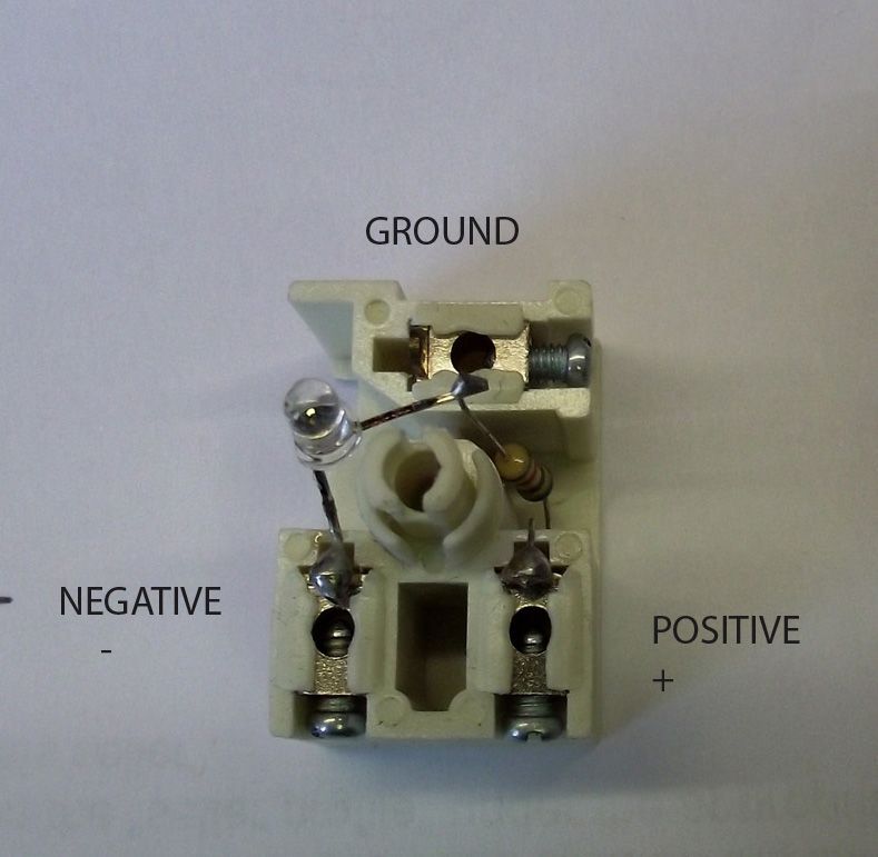
And yes the LED is not connected to the ground, just from + to -.
A seperate question:
I test wired the switch up to test it out and though that it was odd that when switched up (same as the up in my last diagram) it didnt activate the controller, but did when switched down.
Are they opposite than what common sense would assume? top posts not wired to switch up?
Electric-Tarded
oldspark 
Gold - Posts: 4,913
Gold spacespace
Joined: November 03, 2008
Location: Australia
Posted: March 23, 2013 at 12:21 AM / IP Logged  
Rocker and paddle switches are almost always terminals at opposite end of the switch position. (At least that's how I remember it...)
EG - if the rocker or paddle is (in-) up, it's the bottom terminals that will be connected.
As to why NOW connecting +12V & GND to + & - does not click the beast, I don't know. It should click - unless it is a latching solenoid or it's failed.
If latching (or like a stepper motor), then swapping polarity should unlatch it (ie, +12V to - and + to 0V/GND). And - unless it has some internal spike protecting diode or other circuitry - such a reversal should do no harm. [ Relay coils are non-polar per se; you can connect either end to either polarity. It is only if there is some other polarity sensitive device across the coil - eg, protection diode or other circuit. Or in some actuator type cases where polarity determines which direction the "rod thru the solenoid/coil" moves. ]
There is a 3rd possibility (ie, a center-tapped coil or stepper motor) but that doesn't make sense - not with the LED across + & -, nor with it clicking in your original test.
A DMM set to diode test else resistance can confirm inclusion of polar circuits.
A plain coil should read the same resistance or diode-test voltage/resistance no matter which polarity the DMM leads are connected.   
A circuit or diode should result in a different diode-test drop, or different resistance, when swapping the DMM lead polarity.
I'd expect however that any test on that controller should show merely a coil between + & -, and no connectivity between its GND and + or -. The coil should measure (say) 50 Ohm to a few hundred Ohm. (Coil current being eg 12V or 14.4V etc divided by that resistance.)
However there could be capacitors from GND to + & - that may show as an increasing resistance when connecting the DMM on a high-resistance scale (ending up at infinity or open circuit, else a quite high resistance value). And if other components (also or instead of caps), they should show far higher resistance than that of the + & - coil.
thekid760 
Member - Posts: 9
Member spacespace
Joined: March 17, 2013
Location: California, United States
Posted: March 23, 2013 at 5:10 PM / IP Logged  
I'm not sure what I was doing wrong, but I got it working and built a quick tabletop model before installing on my truck. It will have two different air sources, but for now I tee'd them together and used a boost controller to bleed off some air to the left side as that should be lower psi.
I cant wait to see how it's going to work once on the truck.
The demo video:
pneumatics controller wiring - Page 2 -- posted image.
or the direct video link:
http://s114.photobucket.com/user/Thekid760/media/Cars/1995%20Dodge%20Ram%203500/KDP%20Carnage/Harder%20Better%20Faster%20Stronger/8F4E8F8A-D599-4A34-86FA-BFDEF6ABC8AA-3732-00000471B5BD37DF_zps1e13836e.mp4.html
Electric-Tarded
oldspark 
Gold - Posts: 4,913
Gold spacespace
Joined: November 03, 2008
Location: Australia
Posted: March 23, 2013 at 8:04 PM / IP Logged  
Looks good.
I wonder if that actuator does take more than a few hundred mA - it sounds pretty strong!
Page of 2

Sorry, you can NOT post a reply.
This topic is closed.

  Printable version Printable version Post ReplyPost New Topic
You cannot post new topics in this forum
You cannot reply to topics in this forum
You cannot delete your posts in this forum
You cannot edit your posts in this forum
You cannot create polls in this forum
You cannot vote in polls in this forum

  •  
Search the12volt.com
Follow the12volt.com Follow the12volt.com on Facebook
Wednesday, June 12, 2024 • Copyright © 1999-2024 the12volt.com, All Rights Reserved Privacy Policy & Use of Cookies
Disclaimer: *All information on this site ( the12volt.com ) is provided "as is" without any warranty of any kind, either expressed or implied, including but not limited to fitness for a particular use. Any user assumes the entire risk as to the accuracy and use of this information. Please verify all wire colors and diagrams before applying any information.

Secured by Sectigo
the12volt.com spacer
Support the12volt.com
Top
the12volt.com spacer