the12volt.com spacer
icon

connecting power lock wire to lexus es300


Post ReplyPost New Topic
< Prev Topic Next Topic >
BobyYoo 
Member - Posts: 13
Member spacespace
Joined: June 06, 2003
Location: Canada
Posted: March 30, 2013 at 8:33 AM / IP Logged  
Hi all,
I'm installing a remote start on a lexus es300 1997
Everything is done, except I would like to add the power lock function to this remote start module.
i was told, the two wires are
LOCK|dk. blue/white   |- |org plug bottom of fusebox
UNLOCK|dk. blue       |- |org plug bottom of fusebox
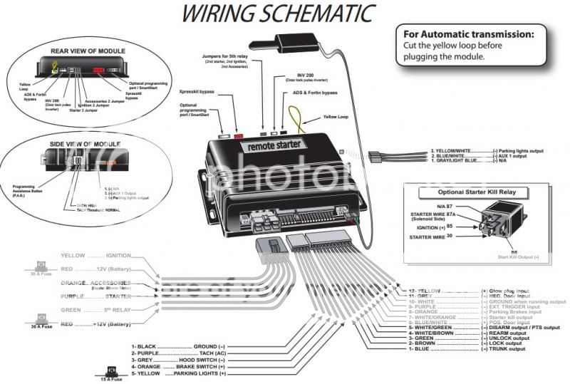
Below is my remote starter diagram
Do I just plug the Green and Brown wire (Lock / Unlock) to the above vehicle wires?
Or is it the WHITE/ brown and WHITE/ green wires that said Rearm / disarm.
I did try to test connecting these wires together and it didn't work.
Do I need a relay? i doubt it.
Bulldog security mention that my power lock is type b, which only mean negative output.
connecting power lock wire to lexus es300 - Last Post -- posted image.
kreg357 
Platinum - Posts: 7,783
Platinum spaceThis member has made a donation to the12volt.com. Click here for more info.spaceThis member has been recognized as an authority in Electrical Theory. Click here for more info.spaceThis member has been recognized as an authority in Mobile Security and Convenience. Click here for more info.spacespace
Joined: January 30, 2009
Location: Pennsylvania, United States
Posted: March 30, 2013 at 8:51 AM / IP Logged  

Yes, the R/S's (-) Lock and Unlock outputs can be directly connected to the ES300's wires.  Here

is some more info to assist you in finding the correct wires :  ( info from Ready Remote )

Power Lock       Dark Blue/White  (-)   @ orange plug, bottom of fusebox  

Power Unlock   Dark Blue  (-) @ orange plug, bottom of fusebox

The lock wires are about 18 gauge.  They will test only by operating the key in the passenger door

lock cylinder, not the rocker switch on the door itself.  On models with keyless entry, find the wires
at the theft module at the front of the center console under the radio.

To test, locate & verify these wires, set your Digital Multi Meter to 20V DC, connect the Red test

lead to +12V constant and the Black Test lead to the suspect wire.  The DMM will read +12V with
a lock/unlock pulse.

The Unlock might require a double pulse.

Here is some more info from Omega :

Lock BLUE/WHITE (-) @ WHITE CONNECTOR IN DRIVERS KICK PANEL
Unlock          RED / GREEN (-)   @  WHITE CONNECTOR IN DRIVERS KICK PANEL*

* RED / GREEN wire requires two pulses to Unlock all doors. First pulse unlocks the Driver Door and disarms the OEM Alarm.

Soldering is fun!
dare_ds69 
Silver - Posts: 419
Silver spacespace
Joined: January 25, 2005
Location: New Jersey, United States
Posted: April 02, 2013 at 12:39 PM / IP Logged  
here is more info:
Power Lock     dk. blue/white     -     org plug bottom of fusebox
     The lock wires are about 18 gauge. They will test only by operating the key in the passenger door lock cylinder, not the rocker switch on the door itself. On models with keyless entry, find the wires at the theft module at the front of the center console under the radio.
Power Unlock     dk. blue     -     org plug bottom of fusebox
     The lock wires are about 18 gauge. They will test only by operating the key in the passenger door lock cylinder, not the rocker switch on the door itself. On models with keyless entry, find the wires at the theft module at the front of the center console under the radio.
how own your mind, control your life.
MECP certified. always use a DMM

Sorry, you can NOT post a reply.
This topic is closed.

  Printable version Printable version Post ReplyPost New Topic
You cannot post new topics in this forum
You cannot reply to topics in this forum
You cannot delete your posts in this forum
You cannot edit your posts in this forum
You cannot create polls in this forum
You cannot vote in polls in this forum

  •  
Search the12volt.com
Follow the12volt.com Follow the12volt.com on Facebook
Saturday, May 4, 2024 • Copyright © 1999-2024 the12volt.com, All Rights Reserved Privacy Policy & Use of Cookies
Disclaimer: *All information on this site ( the12volt.com ) is provided "as is" without any warranty of any kind, either expressed or implied, including but not limited to fitness for a particular use. Any user assumes the entire risk as to the accuracy and use of this information. Please verify all wire colors and diagrams before applying any information.

Secured by Sectigo
the12volt.com spacer
Support the12volt.com
Top
the12volt.com spacer