Astra 4000rs-dbp System Wiring
6-Wire Starter Harness
RED - A: Main Power Input A (+). Connect to the battery or constant power wire at the ignition switch with a minimum 30 Amp supply. Remove the fuse until the installation is complete and all wiring is checked.
RED - B: Main Power Input B (+). Connect to the battery or constant power wire at the ignition switch with a minimum 30 Amp supply. Note: if connecting at the ignition switch it is highly recommended to use separate power wires for each Red wire, each with a minimum 30A supply. Remove the fuse until the installation is completed and all wiring is checked.
BROWN: Second Ignition Output (+). The Brown wire provides +12V for a second ignition wire. This wire may instead be programmed for use as a second accessory or second starter wire.
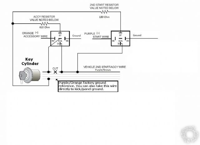
ORANGE: Accessory Output (+). Connect to the accessory wire coming from the ignition switch that supplies power to the heater/air-conditioner. Some cars may have multiple accessory wires.
YELLOW: Ignition Output (+). Connect to the main ignition wire that provides +12V when the ignition is on and while cranking the starter.
VIOLET: Starter Output (+). Connect to the the vehicles starter wire.
16-Pin Main Harness
BROWN / WHITE: Horn Output (-) 500 mA. Connect to a relay to activate the vehicles horn when the alarm is triggered. This wire may instead be programmed as an ignition 3 relay trigger.
BLACK/ GRAY: Tach Input. Connect to the vehicles tach wire or a fuel injector wire if the tachless mode does not provide satisfactory operation.
BROWN: Siren Output (+) 3A. The Brown wire must connect to the sirens red wire. The Black siren wire must be grounded.
GREEN: Negative Door Input (-). Connect to the door switch circuit wire that shows ground when the door is open.
VIOLET: Positive Door Input (+). Connect to the door switch circuit wire that shows +12V when the door is open. This type of door circuit is usually found on Ford vehicles.
YELLOW : +12V Ignition Input. The Yellow wire must connect to a main ignition wire at the ignition harness. This wire must show +12V when the ignition is on and while cranking the starter. The voltage must not drop when the car is starting.
WHITE/ BLACK: Hood Pin Input (-). Connect the to the hood pin switch. The switch must provide a ground output when switch is opened.
BLACK: Ground Input (-). The Black wire must connect to a solid chassis ground. Clean away any paint or dirt to insure the best possible ground.
BLACK/ WHITE: Dome Light Output (-) 500 mA. Connect to the wire that activates the vehicles dome light, usually the door pin switch wire. (see Green and Violet door trigger wires). Note: Must Use Relay.
WHITE/ VIOLET: Factory Disarm Output (-) 500 mA. The Violet/white wire provides a ground output on disarming and before remote starting to disarm a factory security system. Connect to the wire that requires a ground pulse to disarm the factory security system.
BLUE/ORANGE: Ground When Running Output (-) 500 mA. Connect to an optional factory security bypass module if required.
ORANGE: Armed Output (-) 500 mA. The Orange wire provides a ground output while armed to activate a relay for starter defeat and anti-grind protection.
GRAY: Auxiliary 1 Output (-) 500 mA. Connect to a relay for an optional feature such as trunk release, etc. This output may be programmed for momentary, timed, or latched operation.
GREEN / WHITE: Brake Input (+). Connect to the wire that shows +12V when pressing the brake. The GREEN / WHITE wire is a safety shutdown wire that must be connected.
WHITE: Parking Light Output (+/-) relay. Connect the White wire to the circuit that shows +12V or ground only when the parking lights are on and set the internal parking light relay jumper to the proper polarity. For parking light circuits exceeding 10 amps, a relay is required. For vehicles with independent left and right parking light circuits, diodes must be installed to keep the circuits separate. NOTE: Do not connect the WHITE wire to the vehicles headlight circuit.
RED WIRE: Module Power Input (+). Connect to a constant source of +12V.
Plug-in Connectors
5-Pin White Connector: Two Way Receiver Connector.
4-Pin White Connector: Dual stage shock sensor port.
2-Pin Blue Connector: Valet switch port. Mount program switch in an area that is easily accessible from the drivers position.
2-Pin Red Connector: LED port. Mount LED in an area where it may be easily seen from either side of the vehicle.
3-Pin White Door Lock Connector: Door lock port.
· BLUE WIRE - negative unlock output (-) 500mA.
· RED WIRE - (+) Not used
· GREEN WIRE - negative lock output (-) 500mA.
5-PIN White Remote Start Relay Module: Connect to Remote Start 6 Wire Relay Module


 Topic Closed)


 Printable version


