This is a DIY Pictorial for a basic remote start with keyless entry system on a U.S. market 2005 Subaru Impreza with
Automatic Transmission, power locks and no Factory Alarm. The 2003 thru 2007 model years should be similar.
These are very popular cars in cold climates and are easy to integrate an after-market system into. While the major
bypass module manufacturers list a module for this vehicle, no immobilizer system was found. Here is a link to more
info on Subaru immobilizers : http://www.cars101.com/subaru/keyless.html#05%20legacy%20program%20remotes
These vehicles do not have built-in Anti-Grind or one touch starting. Running in Tach Mode is recommended and the
addition of an anti-grind relay circuit is an option.
An Ultra Start U1272 was chosen for this install but any quality remote start system can be used. Verify that the vehicle
does not have a Factory Alarm. The Factory Alarm is listed as being controlled ONLY from the Factory FOB's. With the
owners permission, the owners manual has instructions for turning off the Factory Alarm.
Disassembly :
Remove the lower dash panel by removing the one plastic fastener and two Phillips screws shown in the photos
below. Then pull the panel straight away along the top edge ( 3 fasteners ).
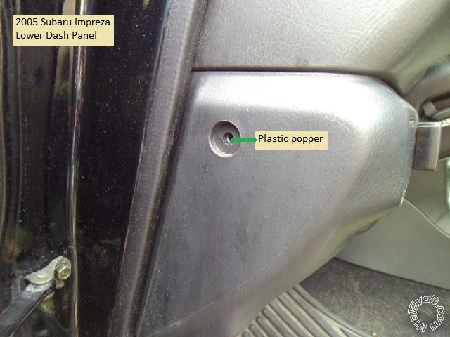
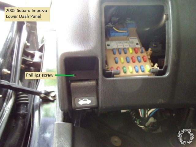
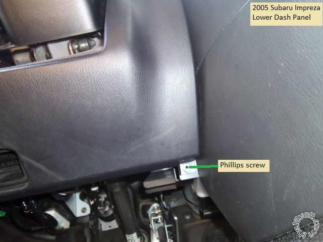
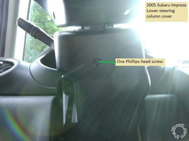
Remove the lower steering column cover by removing the one Phillips screw shown the picture, then gently separate
the two halves ( place the tilt lever in the down position to assist in cover removal ).
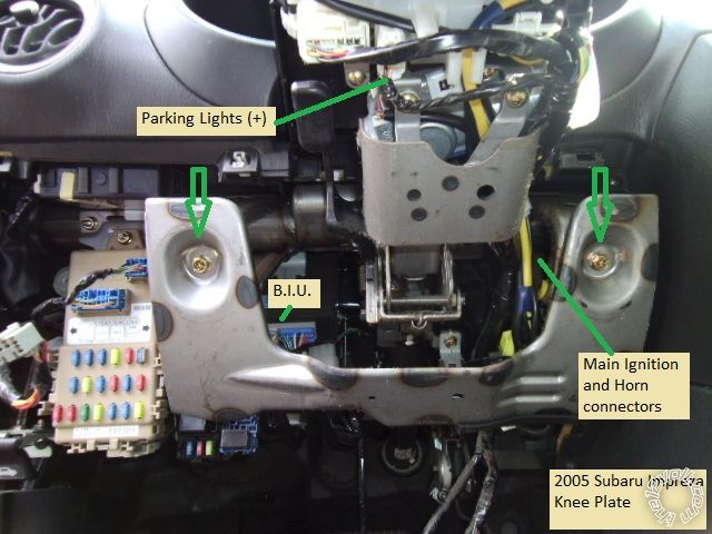
Next, remove the knee brace panel by removing the two 10mm machine screws shown below. ( some important
locations are also noted for further use )
Wiring :
Here is the wire connection list for the 2005 Impreza and the U1272 remote starter :
U1272 connections 2005 Subaru Impreza
6 Pin Ignition Harness
1 Yellow (+) Starter Output BLACK / YELLOW @ upper Ignition harness
2 Green (+) Accessory Output BLACK/ Blue @ upper Ignition harness
3 Red (+) +12V constant BLACK/ White @ upper Ignition harness
4 Red (+) +12V constant BLACK/ White @ upper Ignition harness
5 White (+) Flex Relay Output Not needed
6 Blue (+) Ignition Output Black @ upper Ignition harness
2 Pin Harness
Black (-) Main Chassis Ground Chassis Ground
White Selectable Parking Light Output Orange wire in White 4 Pin Plug @ steering column ( set R/S for (+) output )
9 Pin Harness
1 Yellow (-) Rearm Output Not used
2 Brown (-) Disarm Output Not used
3 Black (-) AUX1 Output Not used
4 RED / White (-) Trunk Release Not used
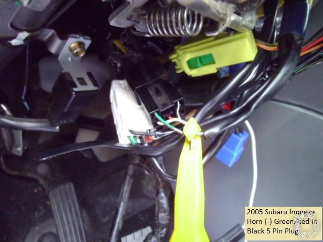
5 WHITE/ Blue (-) Horn Output GREEN/ Red @ Black 5 Pin plug on right side of steering column
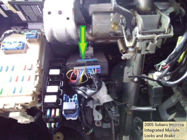
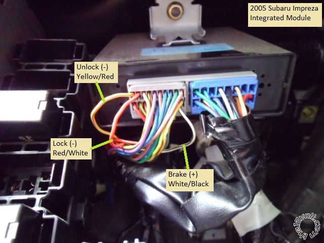
6 Pink (+) Brake Input WHITE/ Black @ Integrated Module
7 GREEN / WHITE (-) Hood Pin Input Hood Pin supplied in kit or upgraded tilt switch
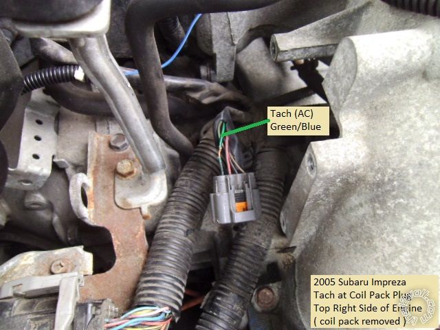
8 Blue/White (AC) Tach Input GREEN/ Blue at 4 Pin coil pack plug
9 Blue (+/-) Glow Plug/WTS/Trigger Input Not used
Lock Harness
Green (-) Lock RED / White @ Integrated Module
Blue (-) Unlock Yellow/Red @ Integrated Module
3 Pin Bypass Harness
Red +12V Not needed
BlackGround Not needed
WHITE/ Violet (-) GWR Not needed ( could be used for Anti-Grind with extra relay )
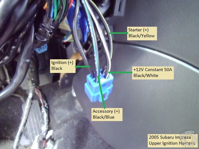
This is a photo of the upper Ignition harness and wires ( disconnected from the lower harness ). Please note that the
wire colors change in the lower harness.
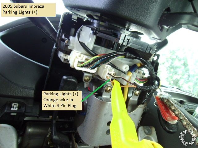
Here is a shot of the Parking Light wire.
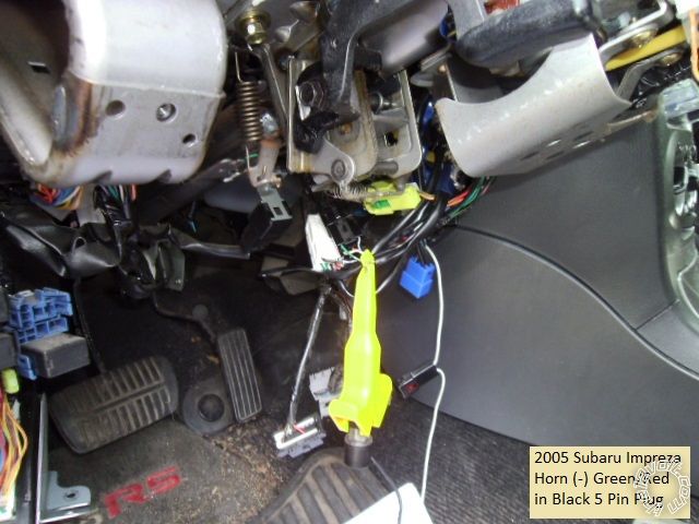
The photos below are the Horn wire.
The next pictures are of the Integrated Module and the wires found there.
Firewall pass thru can be found at a couple of spots. The easiest is a large diamond shaped grommet located high
in the firewall to the right of the steering column and above the gas pedal.
The Tach signal can be found in several places. Inside the vehicle at a connector at the back of the instrument panel
and at the ECM. The ECM is located in the passenger side, below the glove box. For this install, the Tach signal at the
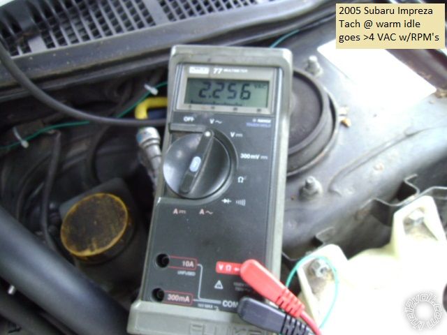
engine coil pack was used, as shown below.
This Tach wire provided a good signal as indicated in the picture below.
There are many good chassis ground locations and plenty of room to secure the remote start module. Remember,
this is only a guide of one way to install a remote starter system. As mentioned, most of the needed wires can be
found in other locations. All wires should be verified with a Digital Multi Meter prior to making quality solder connections.
Soldering is fun!
 Printable version


 Remove the lower steering column cover by removing the one Phillips screw shown the picture, then gently separate
the two halves ( place the tilt lever in the down position to assist in cover removal ).
 Next, remove the knee brace panel by removing the two 10mm machine screws shown below. ( some important
locations are also noted for further use )
 Wiring :
Here is the wire connection list for the 2005 Impreza and the U1272 remote starter :
U1272 connections 2005 Subaru Impreza
6 Pin Ignition Harness
1 Yellow (+) Starter Output BLACK / YELLOW @ upper Ignition harness
2 Green (+) Accessory Output BLACK/ Blue @ upper Ignition harness
3 Red (+) +12V constant BLACK/ White @ upper Ignition harness
4 Red (+) +12V constant BLACK/ White @ upper Ignition harness
5 White (+) Flex Relay Output Not needed
6 Blue (+) Ignition Output Black @ upper Ignition harness
2 Pin Harness
Black (-) Main Chassis Ground Chassis Ground
White Selectable Parking Light Output Orange wire in White 4 Pin Plug @ steering column ( set R/S for (+) output )
9 Pin Harness
1 Yellow (-) Rearm Output Not used
2 Brown (-) Disarm Output Not used
3 Black (-) AUX1 Output Not used
4 RED / White (-) Trunk Release Not used
5 WHITE/ Blue (-) Horn Output GREEN/ Red @ Black 5 Pin plug on right side of steering column
6 Pink (+) Brake Input WHITE/ Black @ Integrated Module
7 GREEN / WHITE (-) Hood Pin Input Hood Pin supplied in kit or upgraded tilt switch
8 Blue/White (AC) Tach Input GREEN/ Blue at 4 Pin coil pack plug
9 Blue (+/-) Glow Plug/WTS/Trigger Input Not used
Lock Harness
Green (-) Lock RED / White @ Integrated Module
Blue (-) Unlock Yellow/Red @ Integrated Module
3 Pin Bypass Harness
Red +12V Not needed
BlackGround Not needed
WHITE/ Violet (-) GWR Not needed ( could be used for Anti-Grind with extra relay )
This is a photo of the upper Ignition harness and wires ( disconnected from the lower harness ). Please note that the
wire colors change in the lower harness.
 Here is a shot of the Parking Light wire.
 The photos below are the Horn wire.

 The next pictures are of the Integrated Module and the wires found there.

 Firewall pass thru can be found at a couple of spots. The easiest is a large diamond shaped grommet located high
in the firewall to the right of the steering column and above the gas pedal.
The Tach signal can be found in several places. Inside the vehicle at a connector at the back of the instrument panel
and at the ECM. The ECM is located in the passenger side, below the glove box. For this install, the Tach signal at the
engine coil pack was used, as shown below.
 This Tach wire provided a good signal as indicated in the picture below.
 There are many good chassis ground locations and plenty of room to secure the remote start module. Remember,
this is only a guide of one way to install a remote starter system. As mentioned, most of the needed wires can be
found in other locations. All wires should be verified with a Digital Multi Meter prior to making quality solder connections.


 the12volt •
