the12volt.com spacer
icon

viper 5702, 2004 expedition, eddie bauer


Post ReplyPost New Topic
< Prev Topic Next Topic >
mtbr179 
Member - Posts: 2
Member spacespace
Joined: July 30, 2013
Location: Texas, United States
Posted: July 31, 2013 at 12:20 PM / IP Logged  
I am going to attempt to install a Viper 5704 in my 2004 Expedition (Eddie Bauer). I’ve installed plenty of audio systems, but this remote start/security system is a first for me. I’ve done a lot of research and figured out most of it (I think), but there are a few things I’m still unsure of. Any advice would be greatly appreciated. I’ve purchased the Viper 5704 and xpresskit PKALL. I have two original keys to program the bypass module.
Here are the wires I’m having trouble finding a definitive connection for:
1.     H1/4 Parking Light Isolation Wire (WHITE/ Brown)
2.     H2/3 (-) 200mA 2nd Status Rear Defog Out (Blue/White)
3.     H2/5 (-) 200mA Trunk Release (RED / White)
4.     H2/6 (-) Door Trigger Input (N/C or N/O) (Green)
5.     H2/19 (-) Trunk Pin/Instant Trigger In (Blue)
6.     H2/23 (AC) Tachometer Input (GREEN / WHITE)
7.     H3/6 (+) Fused 30amp Ignition 1 Input (Red)
This is my complete installation guide. Like I said, this is my first time attempting a security system installation. If you see any errors, please let me know.
H1 - Main Harness Connector (6 Pin)   
H1/1 12 DC Constant Input     Red                         Light GREEN/ Purple @ Ignition Harness
H1/2 Chassis Ground     Black                       Ground
H1/3 Siren     Brown                       Red wire from Siren
H1/4 Parking Light Isolation Wire     WHITE/ Brown            Not Used
H1/5 Parking Light Output     White                       Brown
H1/6 500Ma ground when output     Orange                     Not Used
H2 - Auxiliary/Shutdown/Trigger Harness (24 Pin)   
H2/1 (-) 200mA Ignition/Flex Con     Pink/White          Not Used
H2/2 (-) Neutral Safety Input     BLACK/ White           Ground
H2/3 (-) 200mA 2nd Status Rear Defog Out     Blue/White            ????
H2/4 (-) 200mA OEM Alarm Disable Output     GREEN/ Black          Not Used
H2/5 (-) 200mA Trunk Release     RED / White            ????
H2/6 (-) Door Trigger Input (N/C or N/O)     Green                  ???? (Diode isolation required for each door)
H2/7 (-) 200mA Dome Light Supervision Out     BLACK / YELLOW          BLACK/ Lt Blue BCM ( not necessary if lights come on with unlock )
H2/8 (-) 200mA Horn Honk Output     BROWN / Black          Dark Blue
H2/9 (-) 200mA Status Output     Dark Blue               To GWR on bypass module
H2/10 (-) 200mA Ignition 1 Output     Pink                        Not Used
H2/11 (-) 200mA Aux 3 Output     WHITE/ Black             Not Used
H2/12 (+) Door Trigger Input     Violet                      Not Used
H2/13 (-) 200mA Aux 1 Output     WHITE/ Violet          Not Used
H2/14 (-) 200mA Aux 2 Output     Violet/Black              Not Used
H2/15 (-) 200mA Aux 4 Output     ORANGE / Black          Not Used
H2/16 (+) Brake Shutdown Input     Brown                    Lt Green
H2/17 (-) Hood Pin Output (N/C or N/O)     Grey                      Hood Switch
H2/18 (-) 200mA Starter Output     Violet / YELLOW        Not Used
H2/19 (-) Trunk Pin/Instant Trigger In     Blue                      Not Used
H2/20 (-) Diesel Wait to Start Input     Grey/Black            Not Used
H2/21 (-) Remote Start/ Turbo Timer     WHITE/ Blue           Not Used
H2/22 (-) 200mA Accessory Output     Orange                  Not Used
H2/23 (AC) Tachometer Input     Violet/White           Pink/White
H2/24 (-) 200mA OEM Alarm Output     GREEN / WHITE           Not Used
H3 - Remote Start Heave Gauge Connector (10 Pin)
H3/1 (+) Ignition 1 IN/OUT     Pink                       Blue/Light Green
H3/2 (+) Fused 30amp Ignition 2     RED / White            Not Used
H3/3 (+) Accessory Output     Orange                   BLACK/ Lt green
H3/4 (+) Starter Output (Car side)     Violet                     RED / Lt Blue (This wire will be cut)
H3/5 (+) Starter Input (Key side)     Green                    
H3/6 (+) Fused 30amp Ignition 1 Input     Red                       ????Lt GREEN/ Purple
H3/7 (+) Ignition 2/ Flex Relay Output     Pink/White            Not Used
H3/8 (+) Flex Relay Input 87A key side     Pink/Black            Not Used
H3/9 (+) Fused 30amp Acc/Starter Input     RED / Black           Lt GREEN/ Purple
H3/10 NO CONNECTION     NONE     Not Used
Door Lock (3 Pin)   
1 (-) 500mA Unlock Output     Blue                       Pink/Lt Green
2 Not Used     Empty                     Not Used
3 (-) 500mA Lock Output     Green                      Pink / YELLOW
viper 5702, 2004 expedition, eddie bauer -- posted image.
Thanks in advance for your advice on this.
offroadzj 
Gold - Posts: 2,043
Gold spaceThis member has made a donation to the12volt.com. Click here for more info.spaceThis member has been recognized as an authority in Mobile Security and Convenience. Click here for more info.spacespace
Joined: June 03, 2005
Location: New York, United States
Posted: July 31, 2013 at 1:20 PM / IP Logged  
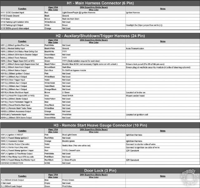
1.     H1/4 Parking Light Isolation Wire (WHITE/ Brown) <--- NOT USED
2.     H2/3 (-) 200mA 2nd Status Rear Defog Out (Blue/White) <---- NOT USED (UNLESS YOU WANT TO CONNECT THE REAR DEFOGGER)
3.     H2/5 (-) 200mA Trunk Release (RED / White) <--- Trunk/Hatch Release      WHITE/ purple (liftgate glass) (rear handle switch)      -      passenger kick or VSM, blue plug, pin 11
Notes: The VSM (Vehicle Security Module) is high in the passenger kick panel.
On vehicles that have the power liftgate open/close use gray/red (-) at the switch in the roof or at the power liftgate module in the left rear quarter panel.
4.     H2/6 (-) Door Trigger Input (N/C or N/O) (Green) <--- ONLY NEEDED IF INSTALLING ALARM -- BLACK / YELLOW      - N.C.      driver kick or VSM, gray plug, pin 4 (MUST SET UNIT FOR N/C DOOR TRIGGER)
5.     H2/19 (-) Trunk Pin/Instant Trigger In (Blue) <--- NOT USED (IF INSTALLING ALARM, TIE TRUNK INTO DOOR TRIGGER FOR EASIER INSTALL)
6.     H2/23 (AC) Tachometer Input (GREEN / WHITE) <--- CONNECT TO ODD COLORED WIRE AT ANY FUEL INJECTOR (ALL INJECTORS WILL HAVE ONE COMMON AND ONE UNCOMMON WIRE; CONNECT TO UNCOMMON WIRE)
7.     H3/6 (+) Fused 30amp Ignition 1 Input (Red) <--- CONNECT ALL 3 30AMP INPUTS (RED, RED / WHITE, RED / BLACK) TO LIGHT GREEN/ PURPLE AT IGNITION SWITCH.
H1/2 Chassis Ground     Black                       Ground <--- USE FACTORY BOLT IN KICKPANEL IF POSSIBLE.
H2/17 (-) Hood Pin Output (N/C or N/O)     Grey                      Hood Switch <--- MUST INSTALL HOOD PIN
HERE IS ANOTHER WIRING LIST. MAKE SURE TO TEST ALL WIRES BEFORE MAKING ANY CONNECTIONS. SOLDER AND TAPE ALL CONNECTIONS
12volts      lt. GREEN/ purple (30A)      +      ignition switch, black 7 pin plug, pin 4
Starter      RED / lt. blue      +      ignition switch, black 7 pin plug, pin 7
Second Starter      N/A           
Ignition      dk. blue/lt. green      +      ignition switch, black 7 pin plug, pin 1
Second Ignition      N/A           
Third Ignition      N/A           
Accessory      BLACK/ lt. green      +      ignition switch, black 7 pin plug, pin 6
Second Accessory      N/A           
Keysense      BLACK/ pink      +      ignition switch, black 7 pin plug, pin 5
Power Lock      pink / YELLOW      -      driver kick or VSM, gray plug, pin 3
Notes: The VSM (Vehicle Security Module) is high in the passenger kick panel.
Power Unlock      pink/lt. green      -      driver kick or VSM, gray plug, pin 2
Notes: The VSM (Vehicle Security Module) is high in the passenger kick panel.
Lock Motor      pink/black      5 wire      driver kick or VSM, gray plug, pin 1
Notes: The VSM (Vehicle Security Module) is high in the passenger kick panel.
Unlock Motor      RED / orange      5 wire      driver kick or VSM, gray plug, pin 7
Notes: The VSM (Vehicle Security Module) is high in the passenger kick panel.
Parking Lights+      brown      +      headlight switch or VSM, green plug, pin 2
Notes: The VSM (Vehicle Security Module) is high in the passenger kick panel.
Also found at the trailer connector, gray 6 pin plug, pin 5. The trailer connector is to the right of the steering column.
Parking Lights-      N/A           
Hazards      same as turn signals           
Turn Signal(L)      lt. GREEN / WHITE (F), lt. GREEN/ orange (R)      +      turn signal switch, gray 8 pin plug, pins 8 and 7
Turn Signal(R)      WHITE/ lt. blue (F), ORANGE / lt. blue (R)      +      turn signal switch, gray 8 pin plug, pins 5 and 6
Reverse Light      BLACK/ pink      +      passenger kick, harness to rear
Door Trigger      BLACK / YELLOW      - N.C.      driver kick or VSM, gray plug, pin 4
Notes: The VSM (Vehicle Security Module) is high in the passenger kick panel.
Dome Supervision      BLACK/ lt. blue      +      driver kick, gray 66 pin plug, pin 59
Trunk/Hatch Pin      WHITE/ purple      - N.C.      VSM, gray plug, pin 12
Notes: The VSM (Vehicle Security Module) is high in the passenger kick panel.
Hood Pin      N/A           
Trunk/Hatch Release      WHITE/ purple (liftgate glass) (rear handle switch)      -      passenger kick or VSM, blue plug, pin 11
Notes: The VSM (Vehicle Security Module) is high in the passenger kick panel.
On vehicles that have the power liftgate open/close use gray/red (-) at the switch in the roof or at the power liftgate module in the left rear quarter panel.
Power Sliding Door      N/A           
Factory Alarm Arm      lt GREEN/ red and yellow/black (driver door keypad)      -      driver kick or VSM, blue plug, pins 9 and 3
Notes: The VSM (Vehicle Security Module) is high in the passenger kick panel.
Factory Alarm Disarm      N/A           
Disarm No Unlock      N/A           
Tachometer      tn, wh, bn/ye, bn/lb, tn/bk, lg/og, tn/rd, or lb      ac      any fuel injector, gray 2 pin plug, pin 1
Wait to start      N/A           
Brake Wire      lt. green or red      +      brake switch or trailer connector, gray 6 pin plug, pin 2
Notes: The trailer connector is to the right of the steering column.
Parking Brake      lt. GREEN/ red      -      driver kick, gray 66 pin plug, pin 13
Horn Trigger      dk. blue      -      horn switch or VSM, green plug, pin 6
Notes: The VSM (Vehicle Security Module) is high in the passenger kick panel.
Memory Seat 1      BROWN / lt. green      -      driver kick, harness to rear
Memory Seat 2      BLACK/ orange      -      driver kick, harness to rear
Memory Seat 3      N/A      -     
Kenny
Owner / Technician
KKD Garage LLC
Albany, NY 12205
mtbr179 
Member - Posts: 2
Member spacespace
Joined: July 30, 2013
Location: Texas, United States
Posted: July 31, 2013 at 10:34 PM / IP Logged  
Thanks for the fast response! I will be installing the alarm as well. I assume I would have to if I don't want to carry the original remote and the viper remote with my keys.
If I end up connecting the defog wire, what am I looking for to connect H2/3 (-) 200mA 2nd Status Rear Defog Out (Blue/White)?
BTW, I noticed you are located in Albany. My brother lives in Clifton Park and, after our discussions about my remote starter, is interested in having one installed in his 2007 Outback. However, he's not willing to attempt to do it himself. Where are you located and approximately how much would it cost him to get one installed in his Outback?
Thanks again for your help!

Sorry, you can NOT post a reply.
This topic is closed.

  Printable version Printable version Post ReplyPost New Topic
You cannot post new topics in this forum
You cannot reply to topics in this forum
You cannot delete your posts in this forum
You cannot edit your posts in this forum
You cannot create polls in this forum
You cannot vote in polls in this forum

  •  
Search the12volt.com
Follow the12volt.com Follow the12volt.com on Facebook
Wednesday, May 29, 2024 • Copyright © 1999-2024 the12volt.com, All Rights Reserved Privacy Policy & Use of Cookies
Disclaimer: *All information on this site ( the12volt.com ) is provided "as is" without any warranty of any kind, either expressed or implied, including but not limited to fitness for a particular use. Any user assumes the entire risk as to the accuracy and use of this information. Please verify all wire colors and diagrams before applying any information.

Secured by Sectigo
the12volt.com spacer
Support the12volt.com
Top
the12volt.com spacer