2004 Neon Remote Start DIY Pictorial. The 2004 and 2005 model years should be the same.
This vehicle was a 2004 Neon with automatic transmission, power locks and no factory alarm. The first thing to check for is the Sentry Immobilizer system. If the ignition keys have a black plastic head, there is no immobilizer system. If the ignition key has a gray plastic head, you have the transponder system and will need a bypass module. There are plenty of bypass modules available for this vehicle. While you could go with a key-wrap or transponder chip type bypass, the newer data style bypass modules are more reliable and offer features that can save you time and trouble during the install.
This car uses a one-wire door lock system. If your remote start system does not have built-in door lock relays or the bypass module does not perform this function, you can use a Directed 451M door lock module. The 451M kit includes the necessary 250 and 1,000 ohm resistors ( vehicles with the Factory Alarm system need 2,700 and 7,500 ohm resistors ). The 451M install guide can be found in the Downloads section of the forum. Follow the Type H wiring diagram.
For this install a Compustar CS600-s remote start w/keyless entry and an iDatalink ADS DL with CH6 firmware was chosen. They were bench prepped using the W2W method for solid reliability. The ADS DL handled the transponder bypass, door locks, trunk release, Factory Alarm ( if installed ), and supplied a Tach signal. Some bypass modules require two working , non-clone, keys for programming. The ADS DL w/CH6 requires only one working key.
Obtaining an ADS DL bypass module with the correct firmware flashed on it could be a problem for the DIYer. The EVO-ALL also needs a specific firmware which would require the Fortin Flashlink cable. The best alternative would be the Fortin INT-SL+ for the transponder bypass and the Directed 451M module for the locks. The INT-SL+ comes pre-loaded and only needs one working key to program.
Disassembly :
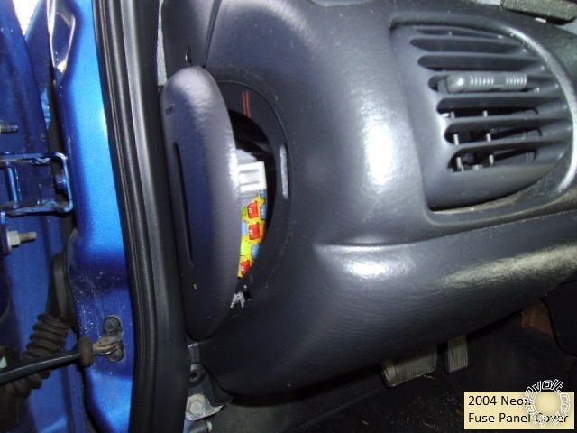
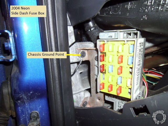
Remove the side dash fuse box cover. This will provide access for a good chassis ground point and makes running the antenna harness to the windshield easier.
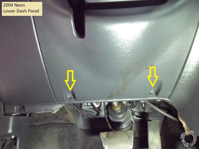
Pop the lower trim piece of the instrument cluster up. Remove the two Phillips screws in the lower dash panel shown below. Then pull the panel straight away from the dash.
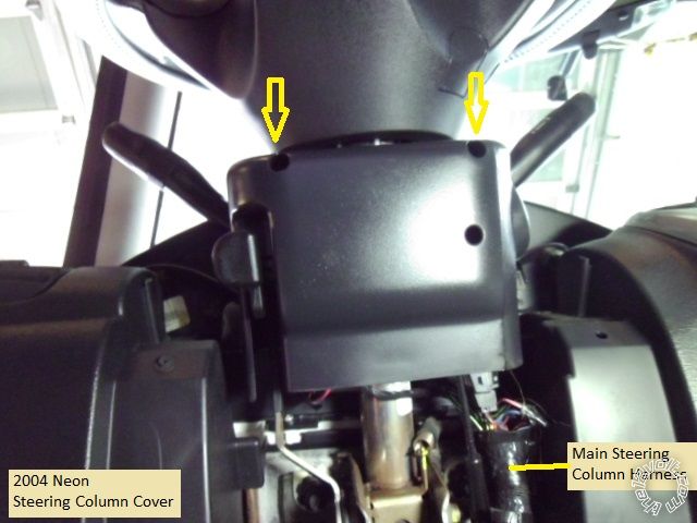
Remove the two Phillips indicated with a long blade screwdriver to separate and remove the steering column cover.
It is not necessary to remove the Drivers Kick Panel to access the door harness and the power lock wire.
Wires :
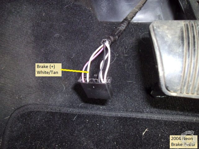
The Brake Pedal wire can be found at the pedal switch connector. Due to limited space, it is difficult to remove the connector without first removing the entire switch assy. Just grasp and turn the switch assy 45 degrees and pull it out. Below is a photo of the Brake wire.
There are many good places to obtain a good Chassis Ground for the R/S system. Below is a photo of my choice.
This vehicle has a tilt steering column. All of the wires listed in the wiring guides as "located in steering column" are grouped together in a large harness running down on the right side of the steering column. The pictures below show the necessary wire at their source but can be found in this large harness, too.
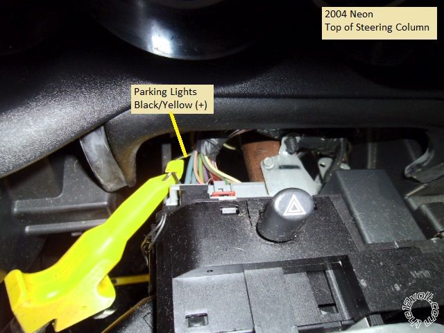
This is a picture of the Parking Light wire.
This is a photo of the Horn wire.
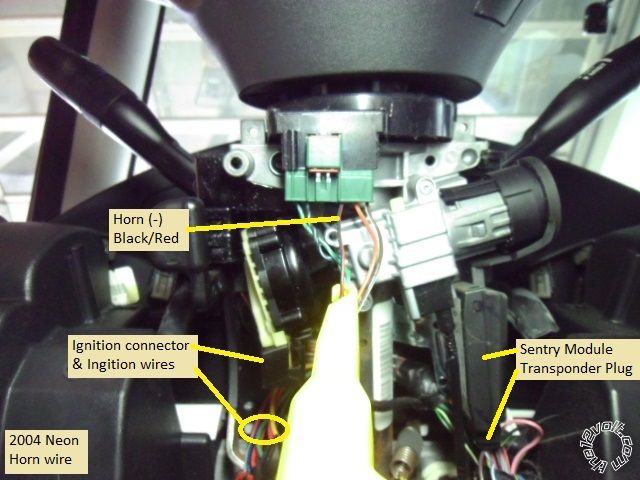
Here is a shot of the ignition connector and the needed wires. Please note that if your Neon has the AutoStick option, there will be a RED / White Ignition2 wire.
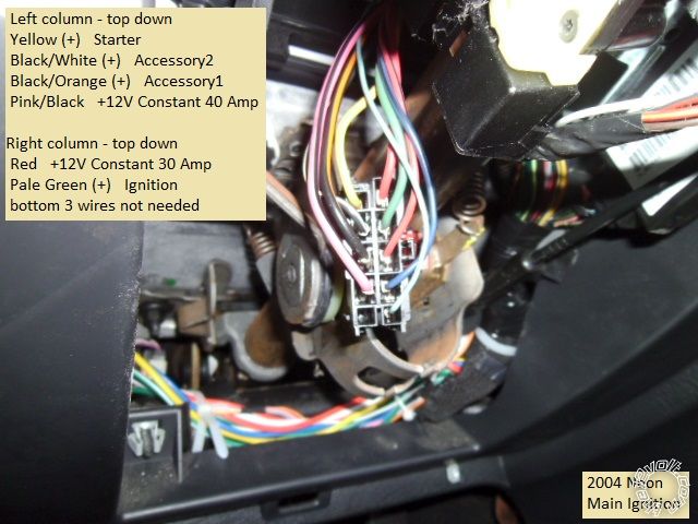
Please note that all of the wire guides list the Ignition wire as Blue. Not sure if it was faded due to age, but this cars Ignition1 wire was Pale Green. Be aware that there is a thin gauge Blue wire in the ignition connector but it tests as +12V constant. This re-affirms the need to test and verify every wire with a Digital Multi Meter to ensure proper installation.
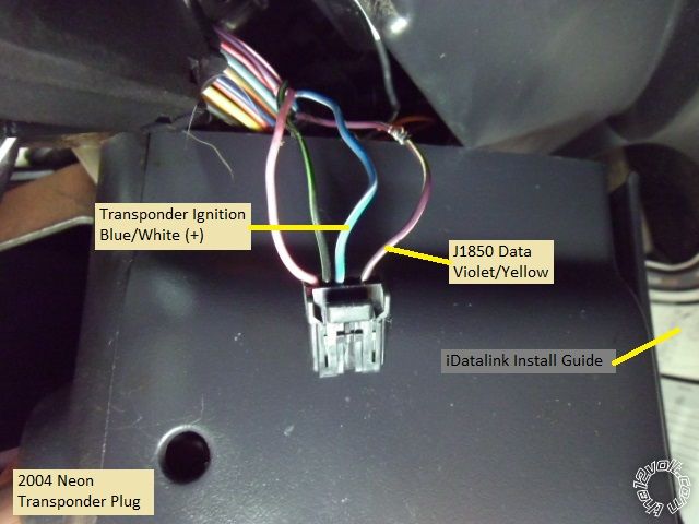
This is a photo of the Sentry Transponder connector. See the Horn photo above for Sentry Module location.
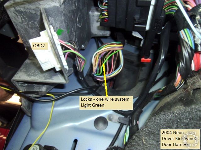
Below is a picture of the Door Lock wire, high in the Driver Kick Panel, in the door harness.
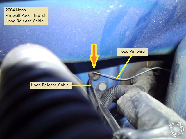
Firewall psss-thru can be made at the Hood Release Cable grommet. This is a picture of the grommet location from the engine compartment side.
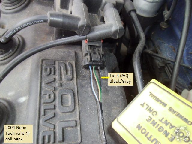
If your install needs a Tach Signal ( Tach Mode is a good idea because this engine does not have "one-touch" starting ), here is a good Tach source.
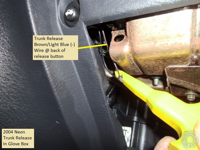
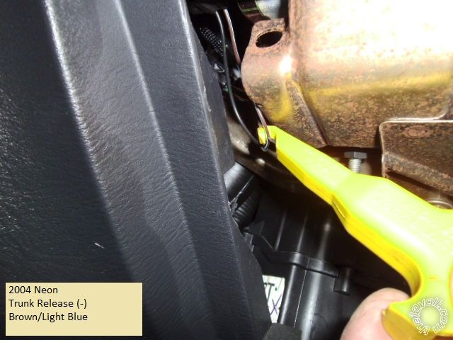
The trunk release button is at the top left corner of the open glove box. If your bypass module does not perform trunk release, here is that wire's pictures :
( For better access, remove the 3 Phillips screws that hold the lower edge of the glove box door, then open the door and release it at the sides and remove it completely.)
The Neon is a popular car and responds well to this upgrade with no surprises.
Soldering is fun!


 Topic Closed)


 Printable version


