the12volt.com spacer
icon

battery drain on excursion


Post ReplyPost New Topic
< Prev Topic Next Topic >
oldspark 
Gold - Posts: 4,913
Gold spacespace
Joined: November 03, 2008
Location: Australia
Posted: November 02, 2013 at 5:55 PM / IP Logged  
Further to above, if the const +12V input takes 5mA, check for other drains from the battery.
Maybe using the high-Amp (20A, else 10A) for an initial confirmation, and then remeasuring on a mA scale once <200mA is confirmed, the way I do it (on the mA scale) is...
- loosen the +ve battery terminal but leave connected.
- the -ve terminal can be used instead if the +ve is too difficult or cluttered.
- with one test probe on the battery terminal and the other on the battery post (either under, or thru the terminal's post hole), remove the terminal.
Hence current continues to flow but thru the DMM.
The reason for the above "no break" measurement is that sometimes after a battery disconnect there is a high inrush current upon reconnection (capacitors for some audio systems; other circuits) that could be too high for the mA range.
BTW - I have learned to carry spare fuses. Many DMMs use a 200mA or 250mA fuse, typically a "205" (20mm x 5mm) type.
02excursion 
Member - Posts: 11
Member spacespace
Joined: October 27, 2013
Location: New Jersey, United States
Posted: November 02, 2013 at 8:00 PM / IP Logged  
oldspark wrote:
I question the +ve lead socket. Usually that furthest left socket is unfused for 10A, or in your case, 20A. The mA ranges use the normal (fused) socket but in your case, the 2nd left "fused mA" socket.
The proper socket can make a big difference. IE - a DMM spec'd with 1% accuracy on a 20A scale can mean 1% of 20A = 200mA which means your 5.21mA could be anywhere from -195mA to 205mA.
If the 5.21mA is correct, then the drain is ok. 5mA is typical of a LED or less, and 1/50th of a typical Automotive relay or 3W bulb.
IOW negligible. (Even some alternators consume over 10mA "parasitically".)
And no - you can't get around that parasitic draw. That is the current required to keep the HU's memory and any supervisory stuff (USB connections etc). IMO HUs should have non-volatile memory (that does not require power) for at least tuning (with a reset button).
The only issue is if that draw varies - eg, my Alpine which when off draws ~120mA-140mA if BOTH const & switched +12V are connected but only a few mA if only one is connected. Hence I can no longer wire BOTH to +12V like I used to do, and hence the relay that connects the switched to const (whenever it is energised by IGN or ACC +12V, or a manual switch, or the HU's remote output).
oldspark,
I will recheck my parasitic draw using the 2nd left "fused mA socket". An aftermarket wiring harness (not sure of the brand) was used to "plug and play" this HU.
My question is where should the remote lead "wire" from the amp be connected too? I was looking at deck and I didn't see a reference for this wire? I'm wondering if somehow my jl audio 1000/1 is getting power when the const +12V is connected via the remote lead and its staying on when the key is on the off position?
I have included a picture below of the deck wiring diagram.
battery drain on excursion - Page 2 -- posted image.
I will upload some additional pictures of where the remote lead is connected to tomorrow if I can find it?
This is driving me nuts.....but i appreciate the help I'm getting here.
Thanks again
02EX
oldspark 
Gold - Posts: 4,913
Gold spacespace
Joined: November 03, 2008
Location: Australia
Posted: November 02, 2013 at 8:27 PM / IP Logged  
The HU "remote" is an output to turn on external amplifiers if fitted. I use it to keep the HU power on when IGN is off by keeping the "connect cont +12V to HU switched +12V".
But are you sure you have a problem? The 5mA drain is ok.
Maybe your batteries dying of age coincided with the new HU and nothing more.
A prudent check may be the batteries themselves. I'd assume BOTH were replaced since permanently paralleled batteries (as well as series for 24V systems) must be matched - certainly not new with old.
Maybe one battery is defective.
A full battery should measure ~12.67V with no load (aka OC - Open Circuit) assuming surface charge has dissipated. (This can read up to ~13.7V and may take 24 hours to dissipate normally, or a few minutes with a load (headlights etc).)
If you isolate the batteries (break their +12V interconnection) they should have the same voltage for days (or weeks) excluding any drains. Either or both yous might have drains - eg, alternator's voltage regulator Sense; HU; alarms; central locking.
02excursion 
Member - Posts: 11
Member spacespace
Joined: October 27, 2013
Location: New Jersey, United States
Posted: November 03, 2013 at 12:09 PM / IP Logged  
Here is today's update....
I found out where the blue remote lead "wire' is connected to ....it's connected to what I believe is an orange wire to the factory wiring harness?
Here is a picture of the back of the factory wiring harness..
battery drain on excursion - Page 2 -- posted image.
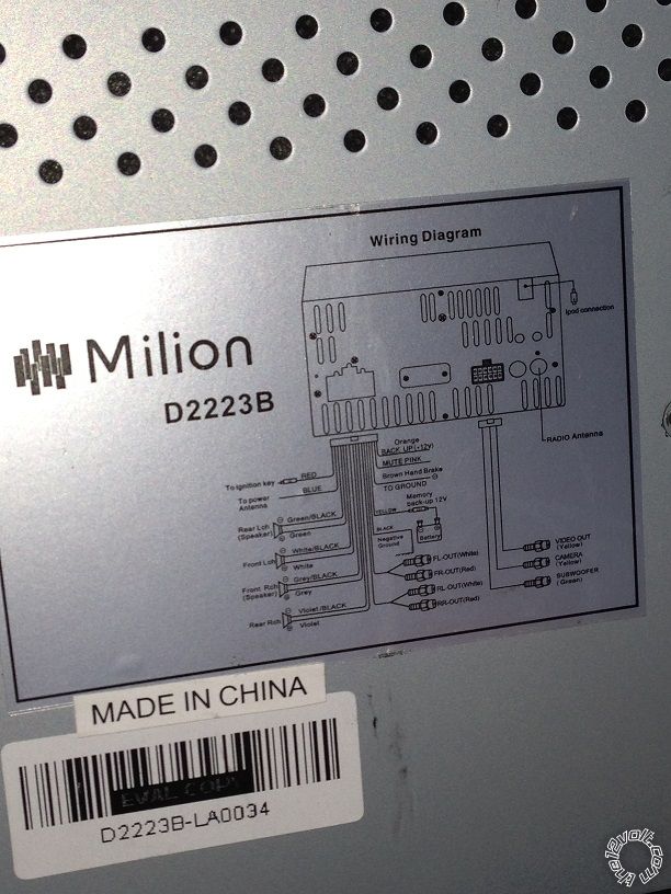
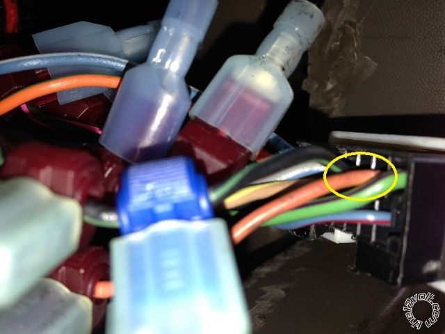
The next pictures are the blue remote lead "wire' from the amp to this orange wire on the factory wiring harness?
battery drain on excursion - Page 2 -- posted image.
Remote lead "wire"
battery drain on excursion - Page 2 -- posted image.
Does anyone have a clue what this orange wire is? also shouldn't this blue remote lead plug into the deck and not the factory wiring harness?
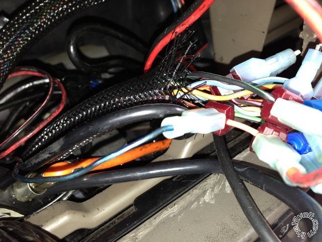
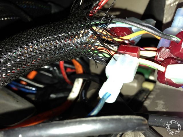
After pulling out the factory wiring harness so i could get a better look at it I've noticed that the previous owner had an aftermarket rear entertainment dvd player and who ever installed it used a combination of quick splice connecters and T-tap connectors onto the factory wiring harness.
Yikes!
Thanks again for the help
02EX
02excursion 
Member - Posts: 11
Member spacespace
Joined: October 27, 2013
Location: New Jersey, United States
Posted: November 03, 2013 at 2:35 PM / IP Logged  
I checked the following below....
Passenger side battery with the EX off
battery drain on excursion - Page 2 -- posted image.
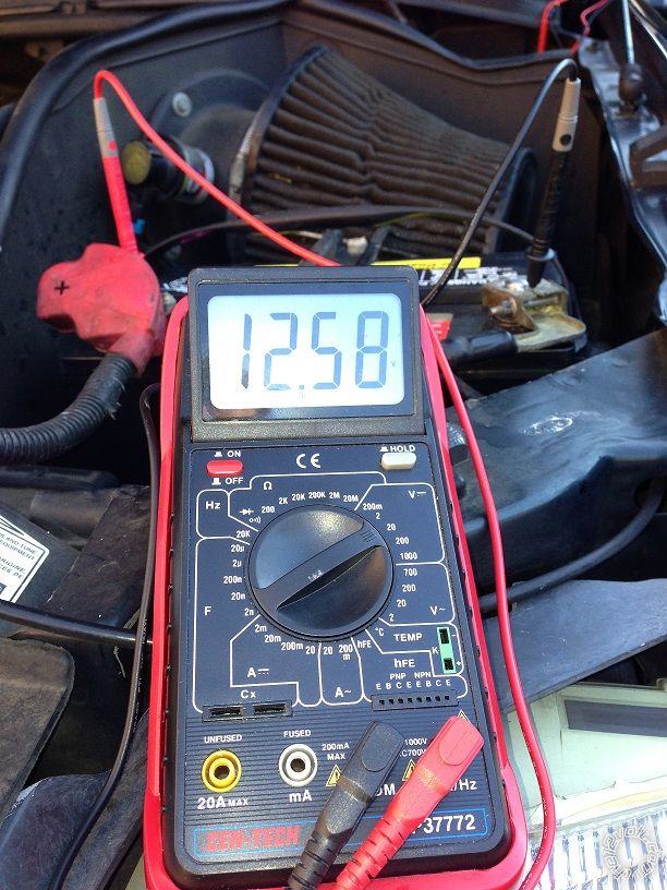
Driver side battery with the EX off
battery drain on excursion - Page 2 -- posted image.
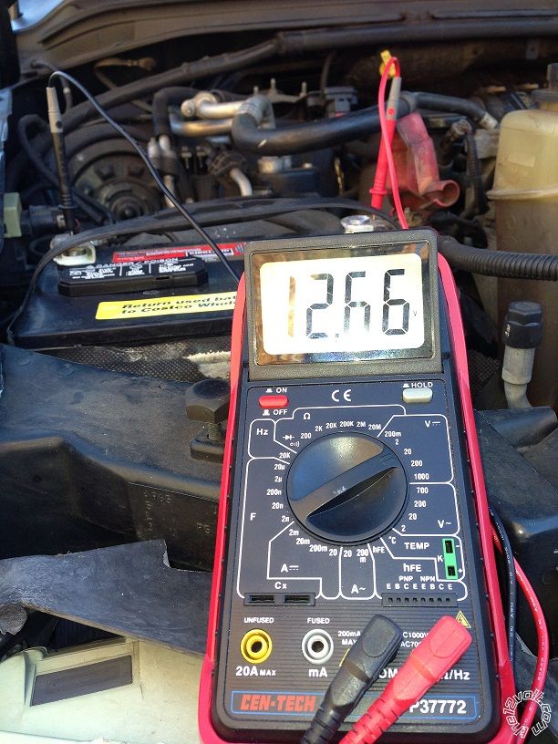
Passenger side battery with EX running
battery drain on excursion - Page 2 -- posted image.
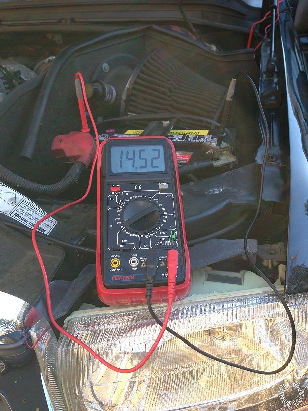
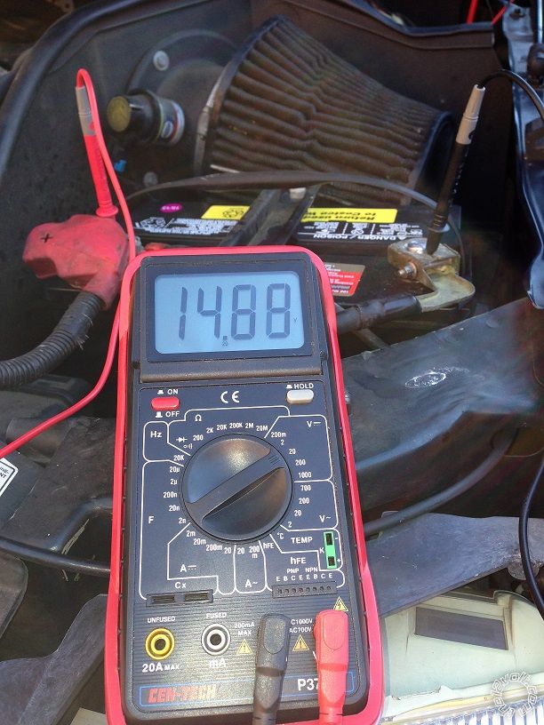
Driver side battery with EX running
battery drain on excursion - Page 2 -- posted image.
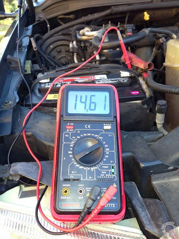
Passenger side battery running with the lights and heater on.
battery drain on excursion - Page 2 -- posted image.
Driver side battery running with the lights and heater on.
battery drain on excursion - Page 2 -- posted image.
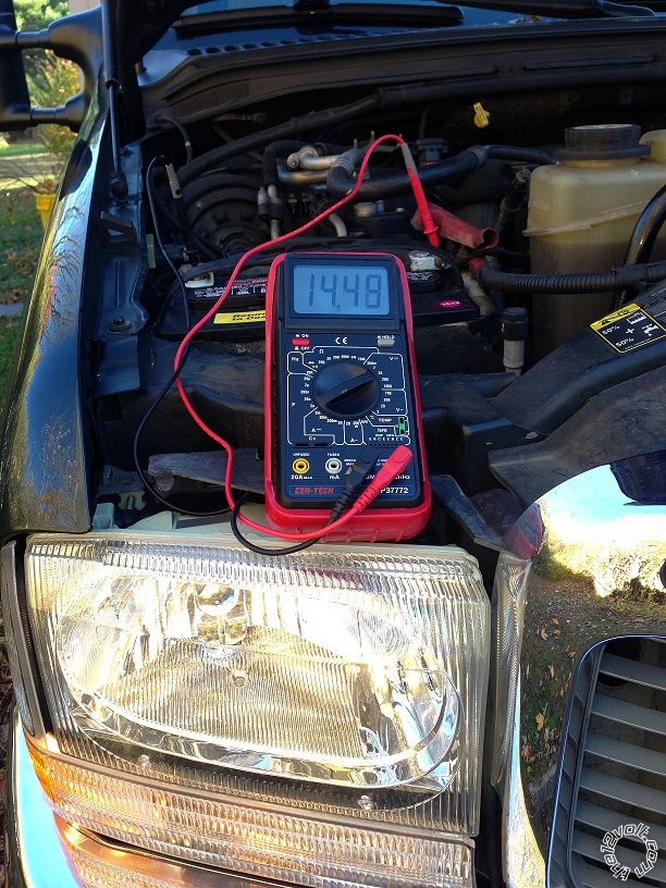
The batteries check fine (which they should they are brand new). The DC power alternator also checks fine as well from the volt test and with the draw on it too.
Thanks again
02EX
oldspark 
Gold - Posts: 4,913
Gold spacespace
Joined: November 03, 2008
Location: Australia
Posted: November 03, 2013 at 9:51 PM / IP Logged  
Your charge voltage is too high. It should be a maximum of 14.4V though initial higher voltages may be acceptable.
Also interesting the voltage differences between the 2 batteries.
12.58V vs 12.66V means an almost 10% SOC (state of charge) difference. Why?
14.88V vs 14.61V might be too high a voltage drop. However both are too high and therefore maybe higher than normal currents.
(14.52V vs 14.48 is still too high and suggests light power is taken from the passenger side/battery.)
Definitely check your alternator as those voltages will boil wet cells and ruin sealed batteries.
If it has a Sense (S) wire, ensure it is intact and properly connected to the battery +12V.
Many Sense wires have a fuse (typically 7.5A even though they only consume tens of mA at the most).
(Most alternators go high if the Sense is not connected.)
Also check if your battery/engine/chassis ground is ok, tho I expect that to be good since the voltage is more likely to increase with increasing load if there is a bad GND.
But when running, check that the voltage across the battery & battery +12V to chassis/body & the +12V supply to the main fusebox (busbar or inputs) are the same or very close.
Page of 2

Sorry, you can NOT post a reply.
This topic is closed.

  Printable version Printable version Post ReplyPost New Topic
You cannot post new topics in this forum
You cannot reply to topics in this forum
You cannot delete your posts in this forum
You cannot edit your posts in this forum
You cannot create polls in this forum
You cannot vote in polls in this forum

  •  
Search the12volt.com
Follow the12volt.com Follow the12volt.com on Facebook
Tuesday, May 14, 2024 • Copyright © 1999-2024 the12volt.com, All Rights Reserved Privacy Policy & Use of Cookies
Disclaimer: *All information on this site ( the12volt.com ) is provided "as is" without any warranty of any kind, either expressed or implied, including but not limited to fitness for a particular use. Any user assumes the entire risk as to the accuracy and use of this information. Please verify all wire colors and diagrams before applying any information.

Secured by Sectigo
the12volt.com spacer
Support the12volt.com
Top
the12volt.com spacer