the12volt.com spacer
icon

dancing lights


Post ReplyPost New Topic
< Prev Topic Next Topic >
04nata 
Copper - Posts: 358
Copper spacespace
Joined: April 22, 2008
Posted: November 27, 2013 at 10:06 PM / IP Logged  
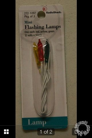
Back in the day we used to buy these lights from Radio Shack, put them in the marker lights or headlights and just turn them on while parked just because. They randomly flash as they warm up and created a flickering/dancing effect.
So I wanted to get them now (20 years later) and use them, just because nobody else does, They are discontinued at Radio Shack and I cannot find them anywhere. I know they have flashing LED's which will work, but what would be the easiest way to make them randomly flash so they are not all just blinking on and off at the same time? Like a list of parts and schematic possibly?
dancing lights -- posted image.
2004 Hyundai Sonata
Kenwood KDC-X599 HU
2-Sundown X-18D4
2-SQ Q4500.1
2-SQ Q90.4
1-Massive DBX4
8-Niche 5.25 mids
8-Niche Tweeters
4-Skar 8" mid-bass
OhioGen 220a alt
OhioGen 350a alt
156.0
powerslave 
Copper - Posts: 126
Copper spacespace
Joined: April 23, 2002
Location: United States
Posted: December 03, 2013 at 11:06 AM / IP Logged  
Give this a shot, I have done it with similar devices:
+12 to LED, LED to one of those Bulbs, Bulb to ground.
Basically, you are using one of those bulbs as your ground path, and once it heats up, will remove ground each time it blinks off.
04nata 
Copper - Posts: 358
Copper spacespace
Joined: April 22, 2008
Posted: December 08, 2013 at 12:49 PM / IP Logged  
Cant do that, I have NONE of these bulbs available
2004 Hyundai Sonata
Kenwood KDC-X599 HU
2-Sundown X-18D4
2-SQ Q4500.1
2-SQ Q90.4
1-Massive DBX4
8-Niche 5.25 mids
8-Niche Tweeters
4-Skar 8" mid-bass
OhioGen 220a alt
OhioGen 350a alt
156.0
powerslave 
Copper - Posts: 126
Copper spacespace
Joined: April 23, 2002
Location: United States
Posted: December 11, 2013 at 11:03 PM / IP Logged  
Then you have to build a random on/off circuit.
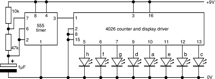
The 4026 IC Timer Chip combines a counter and a seven segment LED driver. The seven-segment outputs plus a divide-by-ten output will drive eight LEDs. While the flashing will not be strictly random, when the lights are properly arranged, they won't have a discernable pattern. This circuit needs only the 4026, a 555 timer, LEDs and a few passive components to make it complete.
dancing lights -- posted image.
04nata 
Copper - Posts: 358
Copper spacespace
Joined: April 22, 2008
Posted: December 12, 2013 at 4:03 AM / IP Logged  

Sweet, thank you.

I recognize the resistors 10k and 47k but whats the 1uF component?

And also I assume that I need 9v LED's or will it work the same with 12volt source and 12 volt LED's?

2004 Hyundai Sonata
Kenwood KDC-X599 HU
2-Sundown X-18D4
2-SQ Q4500.1
2-SQ Q90.4
1-Massive DBX4
8-Niche 5.25 mids
8-Niche Tweeters
4-Skar 8" mid-bass
OhioGen 220a alt
OhioGen 350a alt
156.0
powerslave 
Copper - Posts: 126
Copper spacespace
Joined: April 23, 2002
Location: United States
Posted: December 14, 2013 at 6:28 PM / IP Logged  
1uF is a capacitor.
Not sure on the input voltage at 12V. If you had to, your best bet is a simple voltage regulator circuit using an LM317, 3 terminal voltage regulator and two resistors. They may still have these at Radio Shack or at least they can order one. Shouldn't be too hard to find info about building a simple voltage regulator online.
LEDs can run on variable voltages.
oldspark 
Gold - Posts: 4,913
Gold spacespace
Joined: November 03, 2008
Location: Australia
Posted: December 15, 2013 at 2:02 AM / IP Logged  
Note that the circuit shown does not include buffers or resistors for the LEDs.
The CD4026 is only guaranteed to source or sink ~5mA at ~12V though 20mA is possible.
And I see nothing to indicate current limiting outputs, hence you need to fit resistors etc unless LED current is (maybe?) 20mA or less.
(FYI - the 4026 is a decade counter to 7-segment LED decoder, hence not "random" but 10 different patterns.)
PS - the 4026 tolerates 3V - 18V so it's only the 555 & LEDs you need worry about.
And add at least a decoupling cap for the 555 (0.1uf?) for "correct" operation, tho insufficient dc decoupling/filtering may mean truly random operation...?!)
powerslave 
Copper - Posts: 126
Copper spacespace
Joined: April 23, 2002
Location: United States
Posted: December 16, 2013 at 12:48 AM / IP Logged  
FYI, I have, in the message detail:
The 4026 IC Timer Chip combines a counter and a seven segment LED driver. The seven-segment outputs plus a divide-by-ten output will drive eight LEDs. While the flashing will not be strictly random, when the lights are properly arranged, they won't have a discernible pattern.
Thanks for repeating what I already had...
oldspark 
Gold - Posts: 4,913
Gold spacespace
Joined: November 03, 2008
Location: Australia
Posted: December 16, 2013 at 1:15 AM / IP Logged  
Ah cool, so you can just connect the LEDs without resistor to the 4026 as per your detail.
Oh hang on, are you merely referring to my trivial parenthesised and smallest paragraph, and not the other two key paragraphs...?
If not, I severely apologise for adding info that I thought would prevent circuit failure.
powerslave 
Copper - Posts: 126
Copper spacespace
Joined: April 23, 2002
Location: United States
Posted: December 17, 2013 at 9:45 PM / IP Logged  
I was only referring to what was in Parenthesis, as I did say that info from the beginning.
Page of 2

  Printable version Printable version Post ReplyPost New Topic
You cannot post new topics in this forum
You cannot reply to topics in this forum
You cannot delete your posts in this forum
You cannot edit your posts in this forum
You cannot create polls in this forum
You cannot vote in polls in this forum

  •  
Search the12volt.com
Follow the12volt.com Follow the12volt.com on Facebook
Friday, March 29, 2024 • Copyright © 1999-2024 the12volt.com, All Rights Reserved Privacy Policy & Use of Cookies
Disclaimer: *All information on this site ( the12volt.com ) is provided "as is" without any warranty of any kind, either expressed or implied, including but not limited to fitness for a particular use. Any user assumes the entire risk as to the accuracy and use of this information. Please verify all wire colors and diagrams before applying any information.

Secured by Sectigo
the12volt.com spacer
Support the12volt.com
Top
the12volt.com spacer