the12volt.com spacer
icon

truck cab lights as turn signals


Post ReplyPost New Topic
< Prev Topic Next Topic >
agood1 
Member - Posts: 8
Member spacespace
Joined: February 11, 2007
Location: Georgia, United States
Posted: December 30, 2013 at 9:55 AM / IP Logged  
I'm thinking about making the 2 outside cab lights on my truck blink with the turn signals. I got it figured out as long as the cab lights are turned on. Basically, i will have the trigger from the OEM turn signals open the circuit on the cab lights which was turn off the cab light. This will cause the cab light to blink opposite of the OEM lights, but I'm ok with that. Then problem comes in when I don't have the cab lights turned on.
I don't need a flasher in the circuit, since the signal will come from the OEM lights.
davep. 
Gold - Posts: 641
Gold spacespace
Joined: May 27, 2011
Location: California, United States
Posted: December 30, 2013 at 10:49 PM / IP Logged  
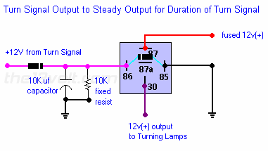
I know how to do it. Use the following circuit for each side. You will need two relays, and two sets of capacitors / resistors. Be sure to use the front turn signals for input, as the rear lights are also brake lights.
When the running lights are on, the cab lights will illuminate normally. When a turn signal is commanded, the turn input will close the relay coil (86), and connect the cab light (30) to the turn signal input (87). The capacitor will hold the relay closed, and the cab light will blink with the turn signal. About 3 seconds after the last turn signal pulse is received, the capacitor will discharge, and the relay will return the cab light to the running lights position (87a). When running lights are off, the cab lights will flash in sync with the turn signals.
Jumper 86 to 87. (Ignore the "battery 12 volt").
30 = cab light
85 = ground
87a = running lights
truck cab lights as turn signals -- posted image.
agood1 
Member - Posts: 8
Member spacespace
Joined: February 11, 2007
Location: Georgia, United States
Posted: December 31, 2013 at 7:48 AM / IP Logged  
ok, I think I understand. Couple questions
Is there a component across terminals 86 and 85? The diagram shows what looks like a resistor, and the same symbol is on the "+12 line from turn signals".
I assume you mean ignore the red line marked "fused 12v(+)?
The cab lights are LED, will that make any difference in the cap or resistor values?
Thanks!
davep. 
Gold - Posts: 641
Gold spacespace
Joined: May 27, 2011
Location: California, United States
Posted: December 31, 2013 at 11:29 AM / IP Logged  
Is there a component across terminals 86 and 85? The diagram shows what looks like a resistor, and the same symbol is on the "+12 line from turn signals".
Those are diodes. I'm not sure why the author included the one across 85-86. The one in the "input from turn signals" must be there, or the cap will discharge into the turn signal bulb filaments.
I assume you mean ignore the red line marked "fused 12v(+)?
Yes.
The cab lights are LED, will that make any difference in the cap or resistor values?
I don't think so. The cap value is determined by the relay coil resistance, and the time duration desired. I've used this circuit, and the time-on is about 3 seconds when used with a 'typical' 30/40A cube relay.
Thanks!
You're Welcome.
agood1 
Member - Posts: 8
Member spacespace
Joined: February 11, 2007
Location: Georgia, United States
Posted: December 31, 2013 at 11:45 AM / IP Logged  
ok, are you sure about a 10k capacitor? Thats pretty big and not carried at the local radio shack.
agood1 
Member - Posts: 8
Member spacespace
Joined: February 11, 2007
Location: Georgia, United States
Posted: January 02, 2014 at 9:42 AM / IP Logged  
Worked perfect. Thank you very much for the assistance.
davep. 
Gold - Posts: 641
Gold spacespace
Joined: May 27, 2011
Location: California, United States
Posted: January 06, 2014 at 9:54 PM / IP Logged  
agood1 wrote:
Worked perfect. Thank you very much for the assistance.
It's so cool to see feedback regarding the final outcome. I'm glad you figured out your project, and are pleased with the results.
DaveP

Sorry, you can NOT post a reply.
This topic is closed.

  Printable version Printable version Post ReplyPost New Topic
You cannot post new topics in this forum
You cannot reply to topics in this forum
You cannot delete your posts in this forum
You cannot edit your posts in this forum
You cannot create polls in this forum
You cannot vote in polls in this forum

  •  
Search the12volt.com
Follow the12volt.com Follow the12volt.com on Facebook
Saturday, May 11, 2024 • Copyright © 1999-2024 the12volt.com, All Rights Reserved Privacy Policy & Use of Cookies
Disclaimer: *All information on this site ( the12volt.com ) is provided "as is" without any warranty of any kind, either expressed or implied, including but not limited to fitness for a particular use. Any user assumes the entire risk as to the accuracy and use of this information. Please verify all wire colors and diagrams before applying any information.

Secured by Sectigo
the12volt.com spacer
Support the12volt.com
Top
the12volt.com spacer