Re the wiring diagram you linked earlier...
It shows the battery goes thru a 30A fuse to the rest of the bike EXCEPT the startermotor heavy cable which is direct to the battery +12V
when cranking. (See the
starter motor on the top right corner.)
BTW - diagram orientation assumes 'right way up' - ie, landscape mode.
From that startermotor relay 30A fuse it goes (down) to the alternator's voltage regulator; or (left) to the IGN switch.
IGN then switches 30A +121V to Fuse #1 (10A) & direct down to the
fan motor whose
fan switch connects it to GND;
and to fuses 2, 3, & 4 for +12V to all other circuits(10A, 15A, 10A).
In short, every OEM electric load in that diagram requires the IGN to be on except PERHAPS the fan motor especially if IGN switch does more than simple on-off (eg, off-acc-IGN, Park-off-IGN).
And of course the starter motor heavy +12V terminal which is connected direct to the batt's +12V terminal.
IMO you do want it switched thru IGN hence either power from one of those switched fused circuits 2, 3, or 4 (see below) else similarly switch a 4 or 5 pin aka SPST or SDPT relay coil to connect its Common 30 - the
Dual Socket Power +12V...
and NO Normally Open 87 via your added 7.5A fuse with maybe a 10A or 30A distribution rating.
Ideally you'd know the max else typical load on any fuse and decide which has the best spare capacity. (If total fuse amperage is exceeded, it could take seconds or hours to blow.)
Otherwise take a chance and move if necessary,
Or if the fuse holder etc and all the wiring off the 10A fuses is suitable for - and hopefully the same as existing - 15A circuit wiring. If so, it should be acceptable to tap into that +12V feed anywhere and upgrade from a 10A to 15A fuse (and hence have a
known 5A available). But it should not be a critical circuit - eg, headlights, brake lights.
A relay solves all the above in that you can guarantee all the raw current you need up - ignoring battery limits, life & safety aspects - to the limit of YOUR added fused-cable's rating direct to the unfused battery +12V terminals yet IGN off should guarantee all loads are off...
Unless like me you also want a manual bypass so you can charge your
accessories with the IGN off, either diodes between IGN & the manual switch and the relay;
or grounding control - eg, insert a fuse to bypass the IGN key.

As I've been meaning to do to my HU's power relay, but the IGN-on requirement to turn & then stay on independent of the IGN key IMO isn't too bad - unless I'm camping... And electric windows, but they are already on +12V (I learned from my previous mistake!) but that ain't good security...

So, a few considerations or solutions...
I would ignore the claimed "25 amps". How can it be if those sockets are specified to only 15A - and many IMO have failed to meet that - what additional protection is there for sub-25A rated loads many of which will not be fused if rated to carry 15A?
IMHO that's dangerous!.
Hence reduce the single-socket capability to 15A unless it can only handle less. Or try a reasonably safe size (eg 1A or 2A, usually 5A, but above 10A must be checked) and see whilst checking for hotspots (warm wiring or switches or GND connections) a few times and thereafter reasonable intervals.
And oh boy, I don't think my day is one involving good expression...


 Topic Closed)


 But reply when you have your updated schematic etc.
I might have a look at your bike's wiring in the meantime... (That's a MIGHT...)
But reply when you have your updated schematic etc.
I might have a look at your bike's wiring in the meantime... (That's a MIGHT...) I will be using satellite navigation unit occasionally, and vehicle usb adapter to charge phone/tablet etc, so not too much draw.
Many thanks,
I will be using satellite navigation unit occasionally, and vehicle usb adapter to charge phone/tablet etc, so not too much draw.
Many thanks,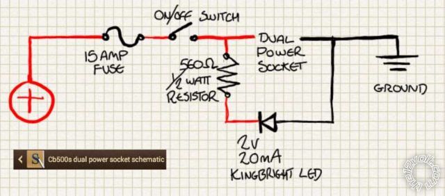 Reverse the LED direction ie, line end (Cathode) towards GND.
And the resistor could be upped to 680 Ohms (1/2W) to ensure the LED's 20mA is not exceeded if running at 14.4V etc. (It shouldn't make a significant difference to brightness.)
I'd probably reduce the fuse size since many cig sockets are likely to flame at 15A; sometimes even 10A, or less - and since your loads will probably be much lower.
Decide your max current draw and add 20-30% and round off to the next available fuse eg 5A, 10A, or even 7.5A.
And to reinforce what I said earlier (and in
Reverse the LED direction ie, line end (Cathode) towards GND.
And the resistor could be upped to 680 Ohms (1/2W) to ensure the LED's 20mA is not exceeded if running at 14.4V etc. (It shouldn't make a significant difference to brightness.)
I'd probably reduce the fuse size since many cig sockets are likely to flame at 15A; sometimes even 10A, or less - and since your loads will probably be much lower.
Decide your max current draw and add 20-30% and round off to the next available fuse eg 5A, 10A, or even 7.5A.
And to reinforce what I said earlier (and in  Printable version


