


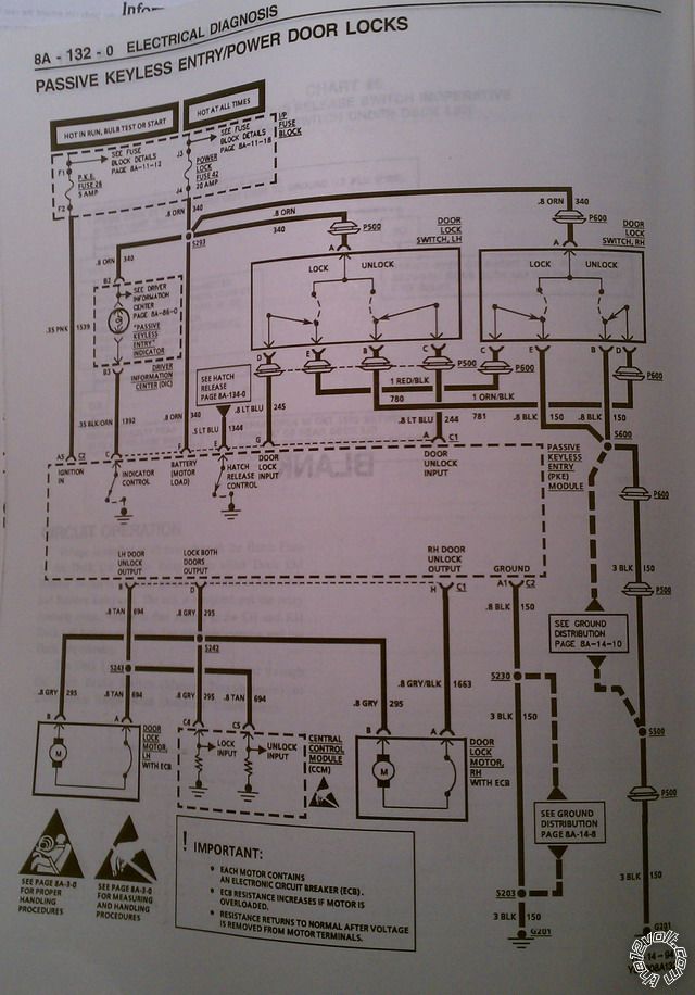
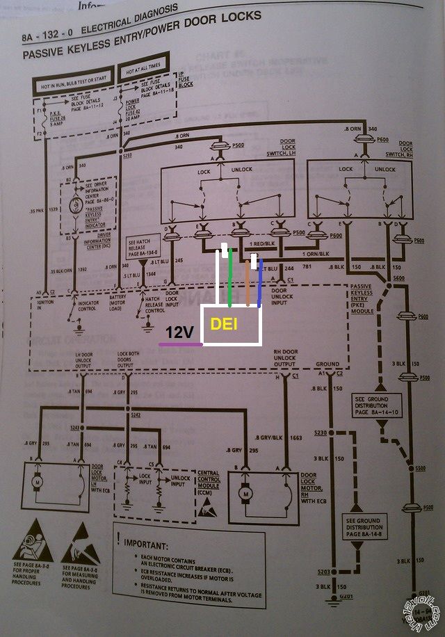
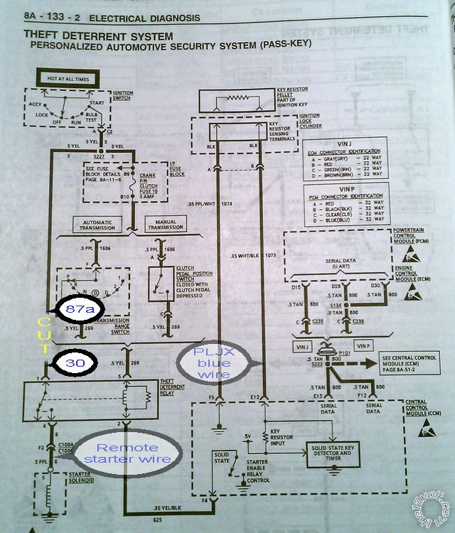
1995 corvette door locks , autopage rs915
Home /
the12volt's Install Bay /
Car Security and Convenience / 1995 corvette door locks , autopage rs915 ( Topic Closed)


Posted: February 23, 2014 at 4:18 PM / IP Logged


Posted: February 23, 2014 at 4:44 PM / IP Logged
howie
(aka: harryharris)


Silver -
Posts: 355
Joined: February 17, 2014
Location: Florida, United States
Posted: February 23, 2014 at 4:57 PM / IP Logged
Posted: February 23, 2014 at 10:25 PM / IP Logged
Posted: March 08, 2014 at 6:09 PM / IP Logged
Posted: March 08, 2014 at 10:50 PM / IP Logged
howie
(aka: harryharris)
Silver -
Posts: 355
Joined: February 17, 2014
Location: Florida, United States
Posted: March 09, 2014 at 1:42 AM / IP Logged
howie
(aka: harryharris)
Silver -
Posts: 355
Joined: February 17, 2014
Location: Florida, United States
Posted: March 09, 2014 at 1:46 AM / IP Logged
Posted: March 09, 2014 at 8:40 PM / IP Logged
Posted: March 09, 2014 at 8:55 PM / IP Logged
 Printable version
| You cannot post new topics in this forum You cannot reply to topics in this forum You cannot delete your posts in this forum You cannot edit your posts in this forum You cannot create polls in this forum You cannot vote in polls in this forum |

| Search the12volt.com |
Follow the12volt.com 
Friday, April 10, 2026 • Copyright © 1999-2026 the12volt.com, All Rights Reserved • Privacy Policy & Use of Cookies

Friday, April 10, 2026 • Copyright © 1999-2026 the12volt.com, All Rights Reserved • Privacy Policy & Use of Cookies
Disclaimer:
*All information on this site ( the12volt.com ) is provided "as is" without any warranty of any kind, either expressed or implied, including but not limited to fitness for a particular use. Any user assumes the entire risk as to the accuracy and use of this information. Please
verify all wire colors and diagrams before applying any information.
