12 Volts WHITE/ red (30A) + ignition switch, white 8 pin plug, pin 7
Second 12 Volts WHITE/ blue (50A) + ignition switch, white 8 pin plug, pin 2
Starter GREEN/ black + ignition switch, white 8 pin plug, pin 8
Second Starter N/A
Ignition BLACK/ red + ignition switch, white 8 pin plug, pin 6
Second Ignition blue / YELLOW + ignition switch, white 8 pin plug, pin 4
Third Ignition N/A
Accessory WHITE/ green + ignition switch, white 8 pin plug, pin 3
Second Accessory N/A
Third Accessory N/A
Keysense GREEN/ YELLOW - Body ECU, white 26 pin plug, pin 14
The Body ECU is under the driver dash, attached to the rear right side of the dash fuse box.
Data Bus yellow (RX), yellow/black (TX) data Transponder Key Amplifier, black 7 pin plug, pins 4 and 5
The Transponder Key Amplifier is around the key switch. The security/immobilizer light wire is PURPLE / white (+) at the instrument cluster, white 20 pin plug, pin 20. The IMO - IMI wires are blue/red - WHITE/ red at the Engine Control Module, white 35 pin plug (E8, second from top), pins 15 and 16. The Engine Control Module is under the passenger dash, behind the glove box.
Can Bus High pink data data link connector, white 16 pin plug, pin 6
Can Bus Low purple data data link connector, white 16 pin plug, pin 14
Can Bus Sw black (door lock data) data Body ECU, white 30 pin plug, pin 24
The Body ECU is under the driver dash, attached to the rear right side of the dash fuse box.
Power Lock blue/white (test with passenger switch) - dash fuse box, rear, white 16 pin plug, pin 5
This wire is only needed if the door locks do not function with the aftermarket system while the vehicle is running. All other times just use the factory alarm arm wire.
Power Unlock blue/orange (test with passenger switch) - dash fuse box, rear, white 16 pin plug, pin 1
This wire is only needed if the door locks do not function with the aftermarket system while the vehicle is running. All other times just use the factory alarm disarm wire.
Lock Motor RED / black to blue/red 5 wire driver kick, white 13 pin plug, pin 6
Driver Unlock Motor BLACK/ white to blue/orange 5 wire driver kick, white 13 pin plug, pin 7
Passenger Unlock Motor blue/black 5 wire driver kick, harness to rear
Parking Lights (-) green - Body ECU, white 26 pin plug, pin 8
The Body ECU is under the driver dash, attached to the rear right side of the dash fuse box.
Parking Lights (+) green + dash fuse box, white 16 pin plug, pin 13
Hazards white - hazard switch, black 5 pin plug, pin 2
Turn Signal (Left) blue/black (F); blue/black (R) + dr kick, wh/gry 43 pin plg, pin 33; dash fusebox, wh 16 pin plg, pin 9
Turn Signal (Right) blue / YELLOW (F); blue / YELLOW (R) + dr kick, wh/gry 43 pin plg, pin18; dash fusebx, wh 16 pin plg, pin15
Headlight red - Body ECU, white 26 pin plug, pin 1
The Body ECU is under the driver dash, attached to the rear right side of the dash fuse box.
AutoLights GREEN/ orange (interrupt to turn off autolights) - Body ECU, white 26 pin plug, pin 3
The Body ECU is under the driver dash, attached to the rear right side of the dash fuse box.
Reverse Light RED / black to RED / yellow + driver kick, WHITE/ gray 43 pin plug, pin 11
Left Front Door Trigger RED / yellow - Body ECU, white 24 pin plug, pin 23
The Body ECU is under the driver dash, attached to the rear right side of the dash fuse box.
Right Front Door Trigger RED / yellow - Body ECU, white 24 pin plug, pin 24
The Body ECU is under the driver dash, attached to the rear right side of the dash fuse box.
Left Rear Door Trigger pink/black - Body ECU, white 24 pin plug, pin 11
The Body ECU is under the driver dash, attached to the rear right side of the dash fuse box.
Right Rear Door Trigger pink/blue - Body ECU, white 24 pin plug, pin 12
The Body ECU is under the driver dash, attached to the rear right side of the dash fuse box.
Dome Supervision white - dash fuse box, white 20 pin plug, pin 8
Trunk/Hatch Pin RED / blue - Body ECU, white 24 pin plug, pin 7
The Body ECU is under the driver dash, attached to the rear right side of the dash fuse box.
Rear Glass Pin N/A
Hood Pin RED / white - driver kick, WHITE/ gray 43 pin plug, pin 41
Trunk/Hatch Release locks/unlocks along with doors
Trunk Release Motor N/A
Fuel Door Release N/A
Power Sliding Door (Left) N/A
Power Sliding Door (Right) N/A
Factory Alarm Arm blue - power window master switch, white 20 pin plug, pin 4
Meter this wire while turning the key in the driver door key cylinder. This wire will also lock the doors.
Factory Alarm Disarm green (double pulse) - power window master switch, white 20 pin plug, pin 14
Meter this wire while turning the key in the driver door key cylinder. This wire will also unlock the doors.
Disarm No Unlock use keysense
Trunk Alarm Shunt N/A
Tachometer BLACK/ white ac data link connector, white 16 pin plug, pin 9
Wait to Start N/A
Neutral Safety N/A
Clutch Pedal N/A
Fuel Pump BLACK/ red + driver kick, white 11 pin plug, pin 3
Rear Defroster red - latched passenger kick, white 22 pin plug, pin 7
Mirror Defroster red - latched mirror heater switch, black 5 pin plug, pin 4
Left Front Heated Seat RED / green + left front seat heater switch, black 6 pin plug, pin 4
Right Front Heated Seat blue/black + right front seat heater switch, white 6 pin plug, pin 4
Speed Sense PURPLE / red ac dash fuse box, white 20 pin plug, pin 5
Also found at the amplifier, white 24 pin plug, pin 11. The amplifier is under the driver seat.
Brake Wire GREEN/ YELLOW + dash fuse box, white 16 pin plug, pin 16
Parking Brake GREEN/ red - Body ECU, white 24 pin plug, pin 2
The Body ECU is under the driver dash, attached to the rear right side of the dash fuse box.
Horn Trigger GREEN/ red - horn switch, black 12 pin plug, pin 6
Wipers blue/black (L), blue/red (H) + driver kick, WHITE/ gray 43 pin plug, pins 14 and 13
Left Front Window (Up/Down) use factory alarm arm/disarm
Right Front Window (Up/Down) see left front window
Left Rear Window (Up/Down) see left front window
Right Rear Window (Up/Down) see left front window
Sun Roof (Open/Close) use factory alarm arm/disarm
Sun Roof (Limit/Close) N/A
Memory Seat 1 blue/orange - Body ECU, white 30 pin plug, pin 20
The Body ECU is under the driver dash, attached to the rear right side of the dash fuse box.
Memory Seat 2 blue/black - Body ECU, white 30 pin plug, pin 2
The Body ECU is under the driver dash, attached to the rear right side of the dash fuse box.
Memory Seat 3 N/A
Radio 12V blue / YELLOW + radio, white 20 pin plug, pin 1
Radio Ground brown - radio, white 20 pin plug, pin 20
Radio Ignition gray + radio, white 20 pin plug, pin 11
Radio Illumination green (parking lights), WHITE/ green (dimmer) +,- radio, white 20 pin plug, pins 2 and 12
Factory Amp Turn-on N/A
Power Antenna black + radio, white 20 pin plug, pin 13
Left Front Speaker (+/-) pink - purple (mid and high); grn - grn/blk (low) +,- amplifier, wht 10 pin plug, pins 2, 6; wht 10 pin plug, pins 2, 9
The amplifier is under the driver seat.
Right Front Speaker (+/-) yellow - black (mid and high); blu - lt. grn (low) +,- amplifier, wht 10 pin plug, pins 8, 7; wht 10 pin plug, pins 1, 5
The amplifier is under the driver seat.
Left Rear Speaker (+/-) black - yellow (door); black - yellow (tailgate) +,- amplifier, wht 10 pin plug, pins 3, 9; wht 10 pin plug, pins 8, 7
The amplifier is under the driver seat.
Right Rear Speaker (+/-) red - white (door); red - white (tailgate) +,- amplifier, wht 10 pin plug, pins 4, 10; wht 10 pin plug, pins 2, 6
The amplifier is under the driver seat.
Center Channel (+/-) green - GREEN/ black +,- amplifier, white 10 pin plug, pins 3 and 9
The amplifier is under the driver seat.
Subwoofer (+/-) blue/red - blue/black (1); blue - lt. green (2) +,- amplifier, white 10 pin plug, pins 1 and 5 (1); 2 and 6 (2)
The amplifier is under the driver seat.
Aux. Audio Input Left (+/-) green - (shield) +,- radio, white 20 pin plug, pins 17 and 16
Aux. Audio Input Right (+/-) red - (shield) +,- radio, white 20 pin plug, pins 15 and 16
RSE Video (+/-) yellow - brown +,- multi-display, white 6 pin plug, pins 1 and 4
RSE Audio Left (+/-) red - green +,- radio, white 12 pin plug, pins 4 and 5
RSE Audio Right (+/-) black - white +,- radio, white 12 pin plug, pins 2 and 3
Satellite Radio 12 Volts
Satellite Radio Ground
Satellite Radio Ignition
Satellite Radio Antenna
Satellite Audio Left (+/-)
Satellite Audio Right (+/-)
Item Size Depth Location
Headunit double DIN center of dash
Left Front Speaker 6 x 9 left front door
Left Front Tweeter 0.8 (tweeter), 2.6 (midrange) left front door
Right Front Speaker 6 x 9 right front door
Right Front Tweeter 0.8 (tweeter), 2.6 (midrange) right front door
Left Rear Speaker 6.0 left rear door
Left Rear Tweeter 2.6 left rear tailgate
Right Rear Speaker 6.0 right rear door
Right Rear Tweeter 2.6 right rear tailgate
Center Channel 2.6 top center of dash
Subwoofer 6.0 right rear quarter panel
Left Front Headrest
Right Front Headrest
Left Rear Headrest
Right Rear Headrest
Satellite Radio Tuner
Gary Sather


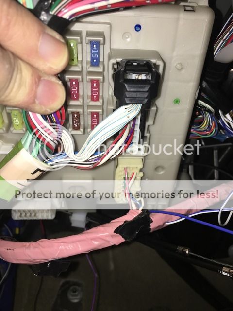 it looks like the top harness in this pic is the 20 pin... but it doesn't look like normal gauge wire going into it. and its hard to probe with it plugged in because of the clip on the top... any ideas?
 Printable version


