The following is a Remote Start and Keyless Entry install Pictorial on the 2007 - 2008 Mazda 3. This vehicle was a 2008 model
with the non-turbo 4 cylinder engine, automatic transmission, power door locks and PATS immobilizer system. There are
many ways to effect an install on this vehicle, here is one.

Any quality remote start with keyless entry system can be used. Some specific vehicle needs :
There are two Accessory type wires in the ignition harness.
This car employees a "one-wire" door lock system.
The PATS transponder can be handled by any one of several good data style bypass modules.
For this install, an Ultra Start U1272 remote start system was chosen. For the bypass duties an XK05 flashed with PKTI
firmware was utilized. Other choices better suited for the DIY'er are the PKALL, Key-OverRide-ALL and the ADS TBSL KO,
as these units require no special / specific firmware flash prior to use. Connections between the R/S and the bypass were
made on the bench in the W2W mode. Below are the connections :
U1272
6 Pin Ignition Harness
1 Yellow (+) Starter Output GRAY/BLACK (+) @ IGNITION SWITCH HARNESS
2 Green (+) Accessory Output PINK / YELLOW (+) @ IGNITION SWITCH HARNESS
3 Red (+) +12V constant BLACK/ RED(+) @ IGNITION SWITCH HARNESS
4 Red (+) +12V constant RED(+) @ IGNITION SWITCH HARNESS
5 White (+) Flex Relay Output YELLOW (+) @ IGNITION SWITCH HARNESS *** Set to ACC2
6 Blue (+) Ignition Output GREEN/ YELLOW (+) IGNITION SWITCH HARNESS
2 Pin Harness
Black (-) Main Chassis Ground Chassis Ground @ Factory Bolt
White Selectable Parking Light Output BLACK/ WHITE (-) @ LIGHT SWITCH Connector *** Set to (-)
9 Pin Harness
1 Yellow (-) Rearm Output Not Used
2 Brown (-) Disarm Output Not Used
3 Black (-) AUX1 Output Not Used
4 RED / White (-) Trunk Release Not Used ( non-electric cable release in car )
5 WHITE/ Blue (-) Horn Output Not Used - at customer request
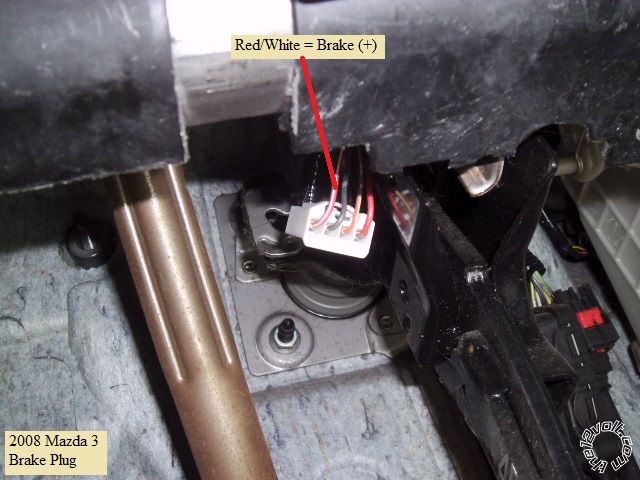
6 Pink (+) Brake Input RED / WHITE (+) @ SWITCH ABOVE BRAKE PEDAL
7 GREEN / WHITE (-) Hood Pin Input to mercury switch mounted to hood hinge bolt
8 Blue/White (AC) Tach Input to any F.I. - to wire that is Black w/stripe
9 Blue (+/-) Glow Plug/WTS/Trigger Input Not Used
Lock Harness
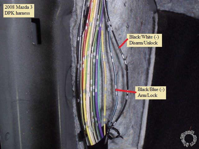
Green (-) Lock BLACK/ Blue (-) @ DKP harness
Blue (-) Unlock BLACK/ White (-) @ DKP harness
3 Pin Bypass Harness
Red +12V XK05 Red wire
Black Ground XK05 Black wire
WHITE/ Violet (-) GWR XK05 Brown wire
XK05 ( wires not previously listed )
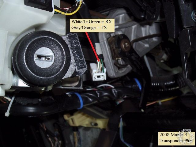
Violet RX output Mazda 3 WHITE/ Lt Green @ transponder harness
Orange TX output Mazda 3 Gray/Orange @ transponder harness
This model Mazda 3 is still fairly easy to disassemble and gain access to all the necessary wires. Start by lifting the
leading edge of the drivers door sill. There is one popper type fastener in the drivers kick trim panel to remove and
then pull the DKP straight back and away.
The lower dash panel on the drivers side is held in place with one Phillips screw and several fasteners. After the screw
has been removed, pull the lower dash panel back & off.
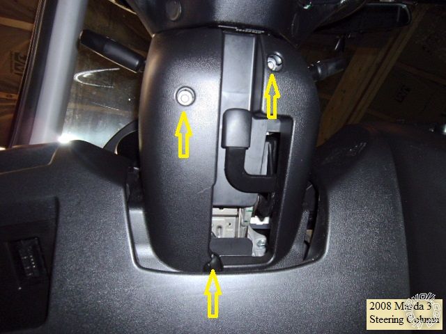
There are 3 Phillips screws holding the two halves of the steering column cover together. Remove the screws from the
bottom cover and separate the two halves. Only the lower cover must be removed and placed aside.
Wires :
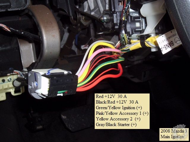
This is a photo of the main ignition connector, removed from the ignition switch with the wires identified :
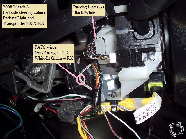
Next is a picture of the left side of the steering column with the Parking Light and the transponder wire locations :
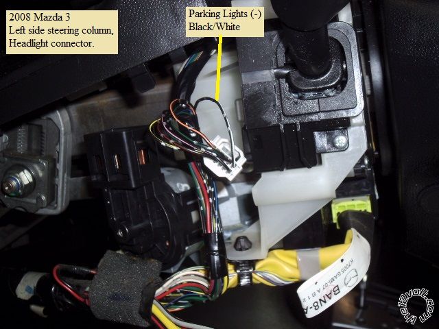
Here is a close up the Parking Light wire ( plug disconnected from the headlight switch ) :
This is a shot of the right side of the steering column and the transponder plug ( disconnected ) with wires marked :
As mentioned above, this car has a "one-wire" door lock system. Typical installs use this wire and a resistor and relays
( if the R/S system does not have internal door lock relays ). I chose to handle the locks via the "drivers door key cylinder"
wires. These wires require a straight (-) pulse. The Unlock wire needs a pulse long enough to unlock the drivers door
and then the other doors. The U1272's Unlock default .72 second pulse was long enough to unlock all the doors. These
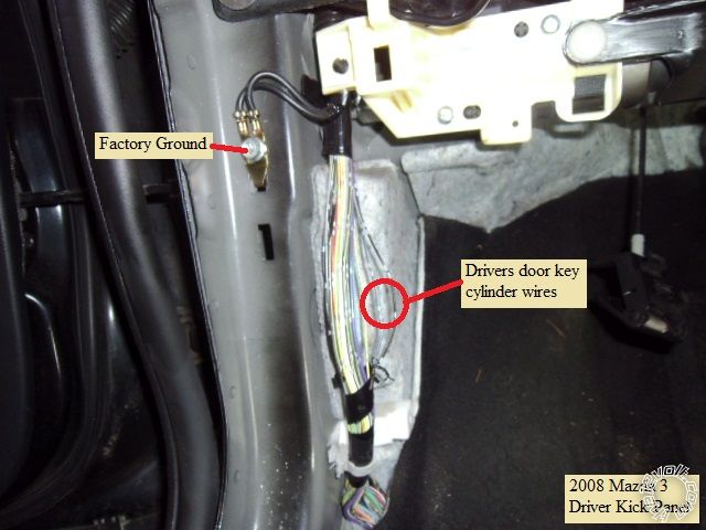
wires will also perform the Arm and Disarm functions if the vehicle has the Factory Alarm system. Below is a picture of the
DKP area with a Chassis Ground point and the DKP harness :
And here is a close-up of the lock wires : ( test for these wires by turning the key in the drivers door key cylinder )
Here is a photo of the Brake wire at the pedal switch connector ( unplugged from the switch ) :
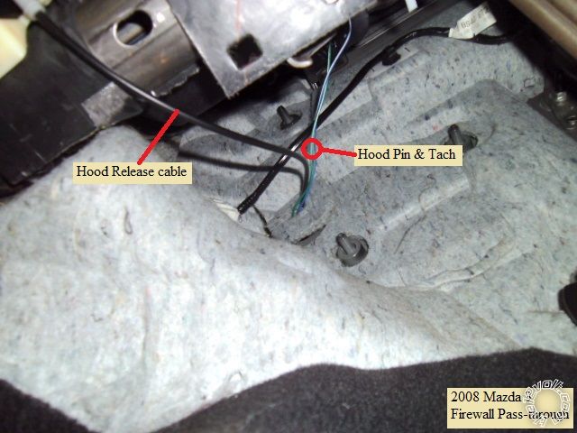
Convenient firewall pass-through can be found under the drivers side dash at the hood release cable grommet shown below :
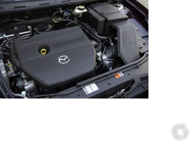
A Tach signal can be found at the Fuel Injectors. They are located below the plastic engine cover. This cover is held in
place with 4 posts, just lift / pull the cover straight up.
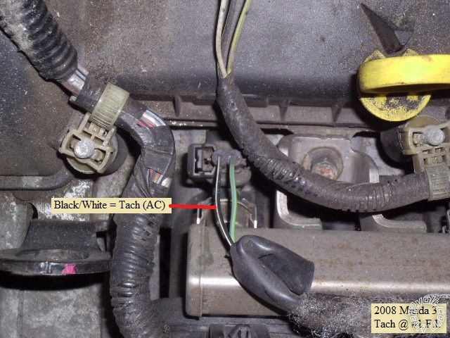
Each injector has two wires. The Tach signal wire is the one that is Black with any color stripe. Pictured below is the
#1 F.I. wire :
This was a basic remote start with keyless entry install, no alarm functionality. Total cost is under $100. Total time
for the DIYer depends on skill level. No special tools are required but a Digital Multi Meter to locate, test and verify
all wires is essential. A decent soldering gun / iron is very important for a durable, quality installation.
Transponder notes:
You will need two working, non-clone, ignition keys to program any of the bypass modules listed above. You can also
use an extra key hidden in a universal "key-in-the-box" style bypass module ( like the DEI 556UW ). Adding additional
ignition keys to the vehicles immobilizer system is fairly easy if you currently have two working, non-clone keys. These
keys are available "online" for under $10. Authorized 12V dealers / installers have special tools and can program a
transponder bypass module using only one working ignition key.
Soldering is fun!


 Topic Closed)


 Printable version


