the12volt.com spacer
icon

avital 4103 parking light connection


Post ReplyPost New Topic
< Prev Topic Next Topic >
billy_hack 
Member - Posts: 9
Member spacespace
Joined: January 13, 2015
Location: New Jersey, United States
Posted: January 13, 2015 at 8:12 AM / IP Logged  

Hi everyone,

I just successfully installed the Avital 4103 Remote Starter on my 2007 Honda.  Everything seems to be working fine, however, I didn't bother to complete the parking light connection from the Avital to the Pilot.  Now I see that it's probably a smart thing to do.  The Avital has a single connection for the parking lights.  The polarity of this output is user-adjustable (+ or -) using a jumper that's supplied with the unit.  The wiring info I have for the Pilot indicates I can control the parking lights with either of 2 connections, 1 needing a positive (+) input, and the other a negative (-).  Can anyone give me advice on which connection point (+ or -) I should connect to on the Pilot?  Are there any pros/cons to either?  Both connections on the Pilot are easily accessible, so that isn't an issue.

Thanks for any help you could provide. 

Billy
vane0804 
Member - Posts: 40
Member spacespace
Joined: November 15, 2007
Location: Illinois, United States
Posted: January 13, 2015 at 8:25 AM / IP Logged  
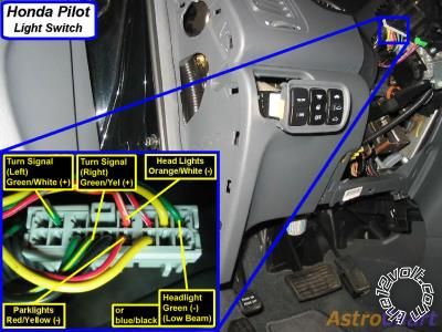
RED / yellow (-) headlight switch, gray 16 pin plug, pin 13
avital 4103 parking light connection -- posted image.
or...
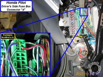
RED / black (+) driver fuse box, green 20 pin plug (D), pin 18
avital 4103 parking light connection -- posted image.
~It's me!
tedmond 
Gold - Posts: 4,610
Gold spaceThis member has been recognized as an authority in Mobile Security and Convenience. Click here for more info.spacespace
Joined: January 06, 2007
Location: Ontario, Canada
Posted: January 13, 2015 at 8:32 AM / IP Logged  
I prefer using negative every time due to the fact its low current. However, in this case the positive lights are easier to get to which is right at the fuse box. Use which ever connection you prefer.
Ted
2nd Year Tier 1 Medical School
Still installing as a hobby...pays for groceries
Compustar Expert
manahawkinrob 
Copper - Posts: 58
Copper spacespace
Joined: February 18, 2008
Location: New Jersey, United States
Posted: January 13, 2015 at 12:37 PM / IP Logged  
I just installed this in my 2011 Civic. I had a little trouble with the polarity jumper. Apparently the documentation has changed a bit and the jumper is on the other side of the D2D connector.
I would set the jumper for whatever polarity you choose, and test the output wire before connection to you lights to verify.
ziggyb222 
Silver - Posts: 593
Silver spaceThis member has made a donation to the12volt.com. Click here for more info.spacespace
Joined: January 04, 2004
Location: Maine, United States
Posted: January 13, 2015 at 12:47 PM / IP Logged  
The jumper settings are printed right on the backside of the brain...makes it nice to double check the polarity!!!
billy_hack 
Member - Posts: 9
Member spacespace
Joined: January 13, 2015
Location: New Jersey, United States
Posted: January 13, 2015 at 12:55 PM / IP Logged  

Holy cow - great responses!  Pictures and everything (Thanks vane0804).  I'll probably go with the negative connection because I prefer the low-current solution as well.  The steering column cover comes off easily enough.  manahawkinrob - good advice.  I'll make sure i do that.

Thanks again!

Billy

Sorry, you can NOT post a reply.
This topic is closed.

  Printable version Printable version Post ReplyPost New Topic
You cannot post new topics in this forum
You cannot reply to topics in this forum
You cannot delete your posts in this forum
You cannot edit your posts in this forum
You cannot create polls in this forum
You cannot vote in polls in this forum

  •  
Search the12volt.com
Follow the12volt.com Follow the12volt.com on Facebook
Tuesday, April 23, 2024 • Copyright © 1999-2024 the12volt.com, All Rights Reserved Privacy Policy & Use of Cookies
Disclaimer: *All information on this site ( the12volt.com ) is provided "as is" without any warranty of any kind, either expressed or implied, including but not limited to fitness for a particular use. Any user assumes the entire risk as to the accuracy and use of this information. Please verify all wire colors and diagrams before applying any information.

Secured by Sectigo
the12volt.com spacer
Support the12volt.com
Top
the12volt.com spacer