the12volt.com spacer
icon

Avital 2101L remote and Spal 2-Door Lock


Post ReplyPost New Topic
< Prev Topic Next Topic >
minkfield 
Member - Posts: 7
Member spacespace
Joined: October 25, 2015
Location: New Hampshire, United States
Posted: October 25, 2015 at 6:48 AM / IP Logged Link to Post Post Reply Quote minkfield
Hello people... I am a new member here and finding this forum is like a light shining in the dark. I am hoping to get some direction from the folks here since none of the equipment I purchased came with instructions. I have two issues but will address them separately in different posts.
First, I purchased a Spal 2-Door central locking kit #37000148 for my 2004 Chevy Silverado along with an Avital 2101L remote kit. I have the Spal kit installed and working properly. Here is the diagram:
Avital 2101L remote and Spal 2-Door Lock - Last Post -- posted image.
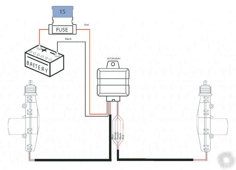
The wires on each activator are split off into two connectors; A two wire connector for the red and blue on the main harness, and a three wire connector for the brown, purple, and black. Now I am hoping to install the Avital remote to lock and unlock the doors (flashing light or horn would be nice but are not necessary) Mostly I just want to be able to activate the locks remotely. The "instructions" with the Avital kit are limited. Basically, there is a pamphlet describing what each colored wire controls but says nothing about how or what they are connected to. The only obvious ones (to me) are the +12v red and the ground. Beyond that, I have no clue how to connect this thing so that it controls my Spal locking system. Since the Spal is a central locking device, and both doors lock and unlock simultaneously, I am guessing (emphasize guessing) that I only need to control one of the Spal actuators?
In any case, I am hoping that someone can give me some guidance on how to wire the remote(s) into this Spal kit.
Thank you so much in advance for any advice!
howie ll 
Pot Metal - Posts: 16,466
Pot Metal spacespace
Joined: January 09, 2007
Location: United Kingdom
Posted: October 25, 2015 at 8:08 AM / IP Logged Link to Post Post Reply Quote howie ll
Install the locks and the SPAL relay. Brown and purple are the trigger wires, ground each in turn to ascertain which is lock and which is unlock.
Avital, purple (violet) and violet/black to ground.
GREEN/ black lock and blue/black unlock.
WHITE/ black, BROWN / black not used.
Here's a couple of hints.
When installing the actuators make sure they move the lock rods freely, SPAL actuators aren't very powerful.
Only use the blue and red wires on the passenger side, wiring up all 5 causes lots of problems if the two motors aren't EXACTLY aligned.
minkfield 
Member - Posts: 7
Member spacespace
Joined: October 25, 2015
Location: New Hampshire, United States
Posted: October 25, 2015 at 8:23 AM / IP Logged Link to Post Post Reply Quote minkfield
howie ll wrote:
Install the locks and the SPAL relay. Brown and purple are the trigger wires, ground each in turn to ascertain which is lock and which is unlock.
Avital, purple (violet) and violet/black to ground.
GREEN/ black lock and blue/black unlock.
WHITE/ black, BROWN / black not used.
Here's a couple of hints.
When installing the actuators make sure they move the lock rods freely, SPAL actuators aren't very powerful.
Only use the blue and red wires on the passenger side, wiring up all 5 causes lots of problems if the two motors aren't EXACTLY aligned.
Thanks for the advice. I was wondering if I needed all five wires on the passenger side. So once I've ascertained lock and unlock on coming from the Spal lock relay, do I simply cut those wires and splice in the appropriate Avital wires?
howie ll 
Pot Metal - Posts: 16,466
Pot Metal spacespace
Joined: January 09, 2007
Location: United Kingdom
Posted: October 25, 2015 at 8:36 AM / IP Logged Link to Post Post Reply Quote howie ll
No, brown and violet on the Spal module are lock unlock relay triggers, join the GREEN/ black and blue/black, no cutting, just connecting.
Install the SPAL part, tested etc. BEFORE proceeding with the 211.
minkfield 
Member - Posts: 7
Member spacespace
Joined: October 25, 2015
Location: New Hampshire, United States
Posted: October 25, 2015 at 8:57 AM / IP Logged Link to Post Post Reply Quote minkfield
howie ll wrote:
No, brown and violet on the Spal module are lock unlock relay triggers, join the GREEN/ black and blue/black, no cutting, just connecting.
Install the SPAL part, tested etc. BEFORE proceeding with the 211.
Sorry... please bear with me but I am confused. Right now, the Spal lock kit is installed and functioning properly. I will need to disconnect (or cut) something to make these connections you speak of. That being said, I DO currently have all five wires connected to the passenger lock, which I need rectify by disconnecting the brown,purple,and black per your instructions.
So are you saying that I should take the unused brown and violet wires (the ones I will be disconnecting from the passenger lock activator) and connect those to the Avital GREEN/ black and blue/black? Also, what is "211?"
howie ll 
Pot Metal - Posts: 16,466
Pot Metal spacespace
Joined: January 09, 2007
Location: United Kingdom
Posted: October 25, 2015 at 9:49 AM / IP Logged Link to Post Post Reply Quote howie ll
Yes.
Forget 211 meant 2110L.
minkfield 
Member - Posts: 7
Member spacespace
Joined: October 25, 2015
Location: New Hampshire, United States
Posted: October 25, 2015 at 10:03 AM / IP Logged Link to Post Post Reply Quote minkfield
Thank you so much! I figured that is what you meant but wanted to be clear. Making those changes today Avital 2101L remote and Spal 2-Door Lock - Last Post -- posted image.
howie ll 
Pot Metal - Posts: 16,466
Pot Metal spacespace
Joined: January 09, 2007
Location: United Kingdom
Posted: October 25, 2015 at 12:18 PM / IP Logged Link to Post Post Reply Quote howie ll
Here you go and bye the way if you've connected 5 wires to both actuators and it works fine then leave it that way.
Look at this, JOIN DON'T CUT. avital_with_spal.png
minkfield 
Member - Posts: 7
Member spacespace
Joined: October 25, 2015
Location: New Hampshire, United States
Posted: October 25, 2015 at 2:33 PM / IP Logged Link to Post Post Reply Quote minkfield
Thanks... Like they say, a picture is worth a thousand words. Too late on the five wires. I already unplugged and pulled them out. I guess I used the wrong word when I said "cut." What I meant was exactly what you show here... cut the sheathing and splice into it. So I now only have the red and blue running into the passenger door actuator. Will that make a difference in functionality?
howie ll 
Pot Metal - Posts: 16,466
Pot Metal spacespace
Joined: January 09, 2007
Location: United Kingdom
Posted: October 25, 2015 at 2:56 PM / IP Logged Link to Post Post Reply Quote howie ll
No it simply means you can only use the key on the driver's side to unlock it.

If you wish to post a reply to this topic, you must first login.
If you are not already registered, you must first register.

  Printable version Printable version Post ReplyPost New Topic
You cannot post new topics in this forum
You cannot reply to topics in this forum
You cannot delete your posts in this forum
You cannot edit your posts in this forum
You cannot create polls in this forum
You cannot vote in polls in this forum

  •  
Search the12volt.com
Follow the12volt.com Follow the12volt.com on Facebook
Saturday, April 27, 2024 • Copyright © 1999-2024 the12volt.com, All Rights Reserved Privacy Policy & Use of Cookies
Disclaimer: *All information on this site ( the12volt.com ) is provided "as is" without any warranty of any kind, either expressed or implied, including but not limited to fitness for a particular use. Any user assumes the entire risk as to the accuracy and use of this information. Please verify all wire colors and diagrams before applying any information.

Secured by Sectigo
the12volt.com spacer
Support the12volt.com
Top
the12volt.com spacer