2011 through 2015 Ford Fiesta remote start install
Here is a quick and easy install for the basic Fiesta. This was a 2012 Fiesta 4 door sedan, with power locks, automatic transmission,
standard key type ignition ( not Push-to-Start ) and no Factory Alarm system.
Vehicle discussion / considerations :
This vehicle vehicle comes with a 40 bit transponder based ignition immobilizer system. The keys have a SA stamp on them. There
are many quality bypass modules available. Some will allow bypass programming with only one factory key but require additional tools
( USB cable ) and access to the respective WEB site for extended programming. The vehicles owner was able to supply both factory
ignition keys, so I choose a Fortin EVO-RIDE bypass module.They come pre-programmed / ready to go right out of the box and are
very reliable & easy to program.
The Ford Fiesta's factory Remote Keyless Entry FOB's continue to work while the engine is running, so a simple / reliable / inexpensive
one button remote start system is all that is needed.
Like most newer Fords, the Parking Lights can be a headache. There are several ways to handle this. You could use the Hazard Lights,
but they would be flashing during the remote start run time. You could get four 1N5404 diodes, split the R/S's (+) Parking Light output
into 4 isolated outputs and make four connections to the Front Right, Front Left, Rear Right and Rear Left Parking Light wires at the
BCM. The other way is to use a relay and make three connections at the Headlight Switch. I did it this way and the actual wiring will
be listed below.
Vehicles without the Factory Alarm system do not have a Hood Pin. While a hood pin is included in the R/S kit, they are the type that
will rust quickly in Northern environments, so a Mercury Tilt switch was installed. No drilling or rust issues.
The rear trunk will lock and unlock with the doors.
These vehicles have a simple single Lock / Unlock button in the center stack, beneath the radio & AC controls. ( Don't ask, it's a
Euro thing. ) Basically a pulse from this switch will flip-flop back and forth between lock and unlock. Using this wire with the R/S's
Unlock wire ( functional only during remote start engine run time ) is the easy way to add functionality ( even though the Factory FOBs
can still be used ).
The Fiesta has "one touch starting" and built in anti-grind. No need for a Tach connection or extra Anti-Grind circuitry.
Considering all of the above, here are the components used for this install :
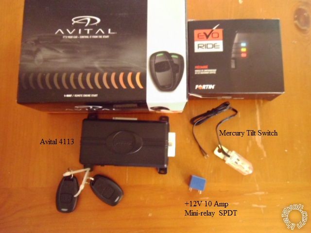
Avital 4113, EVO-RIDE, 12V 10A mini-relay and mercury tilt switch. Total cost = ~ $80
Wiring :
Avital 4113
H1/1 LIGHT GREEN/ BLACK FACTORY ALARM DISARM Not Used
H1/2 GREEN / WHITE FACTORY REARM Not Used
H1/3 YELLOW (+) IGNITION OUT (TO ALARM) Not Used
H1/4 WHITE/ BLUE (-) ACTIVATION INPUT Not Used
H1/5 ORANGE (-) GROUND WHEN LOCKED Not Used
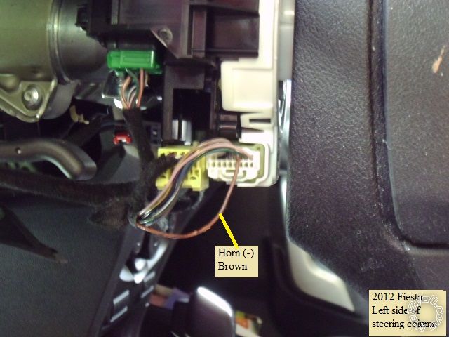
H1/6 BROWN (-) HORN OUTPUT BROWN (-) @ HORN SWITCH
H1/7 RED / WHITE (-) TRUNK RELEASE OUTPUT Not Used
H1/8 BLACK GROUND Chassis Ground
H1/9 WHITE (+/-) LIGHT FLASH * set to (+) with jumper See Relay wiring below
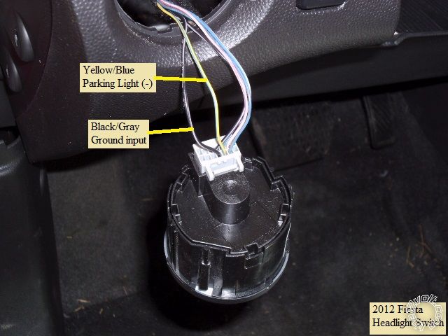
Parking Light wiring ( see photo below for wires ) :
Relay Pin 85 to H1/8
Relay Pin 86 to H1/9
Relay Pin 30 to vehicle side of cut Gray / YELLOW wire at Pin 3 of Gray 10 Pin connector at Headlight Switch
Relay Pin 87a to Headlight switch side of cut Gray / YELLOW wire at Pin 3 of Gray 10 Pin connector at Headlight Switch
Relay Pin 87 to Yellow/Blue wire at Pin 2 of Gray 10 Pin connector at Headlight Switch
H2/1 BLACK/ WHITE (-) NEUTRAL SAFETY SWITCH INPUT Chassis Ground through supplied Valet switch.
H2/2 VIOLET/WHITE TACHOMETER INPUT WIRE Not Used
H2/3 BROWN (+) BRAKE SWITCH SHUTDOWN WIRE BLUE/GRAY (+) @ BRAKE PEDAL SWITCH, GRAY 2-PIN PLUG, PIN 2
H2/4 GRAY (-) HOOD PINSWITCH SHUTDOWN WIRE to Mercury Tilt switch mounted on hood hinge
H2/5 BLUE/WHITE (-) 200mA 2ND STATUS/REAR DEFOG OUTPUT to EVO-RIDE Blue (-) While Running wire
4-pin satellite harness diagram
1 BLUE STATUS OUTPUT Not Used
2 ORANGE (-) ACCESSORY OUTPUT Not Used
3 PURPLE (-) STARTER OUTPUT Not Used
4 PINK (-) IGNITION OUTPUT Not Used
Heavy gauge relay wiring diagram
1 PINK (+) (30 AMP) OUTPUT TO IGNITION CIRCUIT BROWN / YELLOW (+) @ IGNITION SWITCH, BLACK 7-PIN PLUG, PIN 1
2 PURPLE (+) (30 AMP) OUTPUT TO STARTER CIRCUIT BLUE/WHITE (+) @ IGNITION SWITCH, BLACK 7-PIN PLUG, PIN 7
3 ORANGE (+) (30 AMP) OUTPUT TO ACC CIRCUIT PURPLE / GREEN (+) @ IGNITION SWITCH, BLACK 7-PIN PLUG, PIN 6
4 RED (+) (30A) HIGH CURRENT 12 INPUT combined with Red at Pin 6 and fused down to 20 Amps to Battery
5 PINK/WHITE (+) PROGRAMMABLE OUTPUT Not Used
6 RED (+) (30A) HIGH CURRENT 12V INPUT combined with Red at Pin 4
Note : All of the wires at the ignition switch are thin gauge ( 15 Amp ) so these 4113 ignition wires were extended with quality 18 gauge
wire in the same color for vehicle connections.
Door lock harness, 3-pin connector
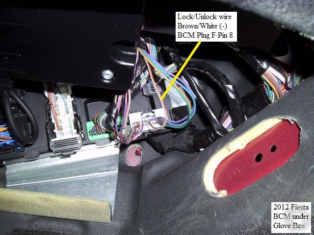
1 BLUE (-) UNLOCK OUTPUT BROWN / WHITE (-) @ BCM, WHITE 24-PIN PLUG(F), PIN 8,
2 EMPTY NOT USED
3 GREEN (-) LOCK OUTPUT Not Used
Note : This Blue Unlock wire was extended by 2 feet to enable connection at the BCM which is behind the glove box.
EVO-RIDE wiring :
4 Pin plug
Cut off twin connector end.
Connect the Red wire to 4113 thick Red
Connect the Black to 4113 H1/8 Black
6 Pin plug
Blue wire to 4113 H2/5 Blue/White wire
Yellow wire to 4113 thick Pink IGN wire
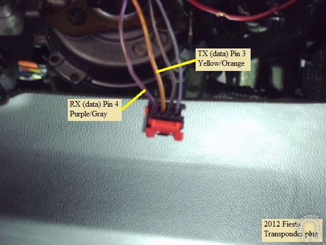
PURPLE / White RX wire to Fiesta PURPLE / Gray RX wire at Transponder plug Pin 4
Yellow/Black TX wire to Fiesta Yellow/Orange TX wire at Transponder plug Pin 3
Note : Interconnections between the 4113, EVO-RIDE and the Parking Light relay can be done prior to install during Bench Prep.
Disassembly :
Remove the Glove Box by opening it, squeezing in at the back corners and then rotating it further down. Next, just pull it straight away
from the dash. Roll the under dash cover out of the way for BCM access.
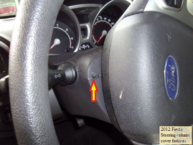
Steering column covers :
Use a T25 Torx driver to remove the 2 screws should at the 10 and 2 o'clock positions. Remove the upper steering column cover by
squeezing in at the side seams to lift the top section up.
Remove the T25 screw in the bottom cover section shown below and remove the bottom cover.
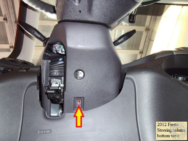
This will expose all the necessary wires.
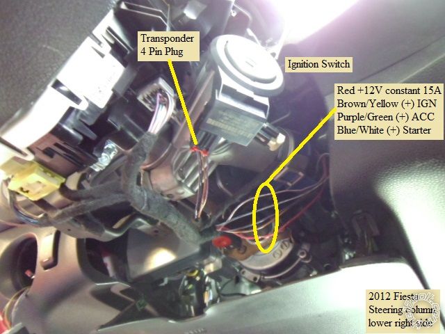
Vehicle connections :
This is a photo of the right side of the steering column with the ignition wires and transponder plug marked.
Next is a close-up of the transponder plug and the wires needed by the EVO-RIDE.
Here is a photo of the left side of the steering column with the Horn wire.
The Headlight Switch assy can be removed by extending the adjustable steering column all the way out and up. Then reach inside the
dash a release the Headlight assy. Below is a shot of the connector and necessary wires.
This is a picture of the BCM as seen below the passenger side lower dash. The door lock flip-flop wire is indicated.
Not shown is the Brake wire. It is slightly difficult to access with out removing the driver knee air bag. At the top of the Brake pedal
there are 2 connectors. The one on the left side is for the cruise control. The Blue/Gray Brake (+) wire is in the plug on the right,
towards the center console. You can reach and unplug the connector through the dash, below the steering column and drop the
plug down for wire connection.
Also not shown is the firewall pass through for +12V power and the hood pin. Above the dead pedal and below the main harness
pass through plug is an unused rounded rectangular grommet about 1.5" by 2.5". It is behind some insulated padding with a pre-cutout
section.
There is plenty of room under the drivers dash for the R/S system. I chose a location that was secure but distant enough from the
ignition switch that required extending those wires. Remember to allow extra harness for the tilt / telescopic steering wheel.
Avital 4113 programming changes :
Menu 1, Feature 1 to Option 2 - 20 mS. Enables horn with short pulse.
Menu 2, Feature 1 to Option 3 - OFF. Vehicle starts under it's own control.
Menu 2, Feature 4 to Option 3 - 1,0 Sec. 4113 sends out a fixed 1 second Starter output. Probably not needed but...
All in all, a nice Saturday project for the DIY'er. Remember to test all wires with a DMM prior to making quality solder connections.
Soldering is fun!


 Topic Closed)


 Printable version


