the12volt.com spacer
icon

2 speed engine cooling fan wiring


Post ReplyPost New Topic
< Prev Topic Next Topic >
glamisguy99 
Member - Posts: 32
Member spacespace
Joined: April 21, 2005
Posted: January 30, 2016 at 3:41 AM / IP Logged Link to Post Post Reply Quote glamisguy99
I'm looking for some advice on hooking up a 2 speed cooling fan in my hotrod. The fan I have has 3 wires, a ground and 2 positives. Low speed is activated by one positive wire and high speed is activated when both positive wires are connected. I will be controlling them with an ON-OFF-ON toggle switch and 2 relays. I've tried to lay out a schematic of how I think the wiring should look.
2 speed engine cooling fan wiring -- posted image.
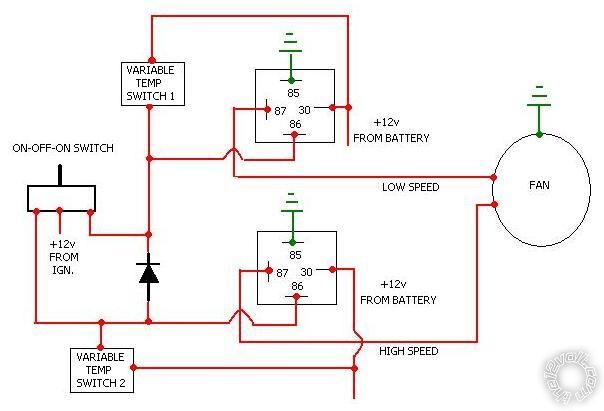
I also have 2 variable temperature switches (the kind with the temp probe and adjusting knob) that I may use to automatically turn it on, one set at a higher temp than the other. I will keep the toggle switch as a backup in case of failure of the temp switches. That schematic would look like this
2 speed engine cooling fan wiring -- posted image.
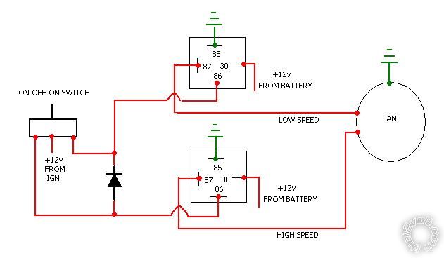
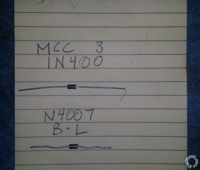
I may omit the second variable switch and just manually engage high speed on demand with the toggle switch. I may also decide to wire the positive inputs on the variable switches to an ignition switched source so the fan will not run when the car is off. Do my schematics look like they will work? They seem fairly simple but is there a better way? I'm not too sure what diode I should use either. Thanks for the help!
geepherder 
Platinum - Posts: 3,668
Platinum spaceThis member consistently provides reliable informationspace
Joined: October 27, 2003
Posted: January 30, 2016 at 7:27 AM / IP Logged Link to Post Post Reply Quote geepherder
It looks good to me. What is the purpose of the diode? Do both low and high speed wires need to be powered in high? If not, you can eliminate it.
I would leave the variable temp switches on constant power. Most cars will allow the cooling fans to run after turning off the engine. If you are worried about the battery draining, you can install an automatic battery cutoff so if the voltage gets below a certain point it will kill power to the car.
My ex once told me I have a perfect face for radio.
glamisguy99 
Member - Posts: 32
Member spacespace
Joined: April 21, 2005
Posted: January 30, 2016 at 12:49 PM / IP Logged Link to Post Post Reply Quote glamisguy99
Thanks for the help. Yes both power wires need to be connected in order for high speed to activate. The diode will prevent the high speed relay from energizing when low speed is activated. I'm not sure what diode I will need but I don't think it needs to be very large since it is only on the trigger side of the relay.
geepherder 
Platinum - Posts: 3,668
Platinum spaceThis member consistently provides reliable informationspace
Joined: October 27, 2003
Posted: January 30, 2016 at 1:28 PM / IP Logged Link to Post Post Reply Quote geepherder
If that's the case, a simple 1-amp rectifying/switching diode will work fine. I used to buy them in a 25-pack at Radioshack.
My ex once told me I have a perfect face for radio.
glamisguy99 
Member - Posts: 32
Member spacespace
Joined: April 21, 2005
Posted: January 30, 2016 at 10:21 PM / IP Logged Link to Post Post Reply Quote glamisguy99
I have 2 diodes on hand and would prefer to use one of them if one will work, however I don't know what the markings tell me. Here's a picture of them with what is written on each of them.
2 speed engine cooling fan wiring -- posted image.
geepherder 
Platinum - Posts: 3,668
Platinum spaceThis member consistently provides reliable informationspace
Joined: October 27, 2003
Posted: January 31, 2016 at 5:24 AM / IP Logged Link to Post Post Reply Quote geepherder
Either one should be fine. If your meter has a diode test, touch your negative probe to the side with a stripe. The other side goes to positive. You should get a reading/audible tone. Reverse the leads and you should get no reading/tone (it may say OL).
If your meter doesn't have a setting for this, you may be able to take a resistance reading. Again, stripe to negative, other to positive, you should get something. The other direction, you shouldn't.
My ex once told me I have a perfect face for radio.
glamisguy99 
Member - Posts: 32
Member spacespace
Joined: April 21, 2005
Posted: February 11, 2016 at 12:09 AM / IP Logged Link to Post Post Reply Quote glamisguy99
Thanks geep, I finally got the fan installed and everything works as it should!
machpilot 
Member - Posts: 15
Member spacespace
Joined: January 14, 2016
Location: Virginia, United States
Posted: February 16, 2016 at 1:45 PM / IP Logged Link to Post Post Reply Quote machpilot
I would recommend using the automatic temp sensors. I built a single speed switched relay setup on mine, and after the first time I forgot to flip the switch on and my motor got to hot I quickly installed a temp sensor to turn it on/off for me.

If you wish to post a reply to this topic, you must first login.
If you are not already registered, you must first register.

  Printable version Printable version Post ReplyPost New Topic
You cannot post new topics in this forum
You cannot reply to topics in this forum
You cannot delete your posts in this forum
You cannot edit your posts in this forum
You cannot create polls in this forum
You cannot vote in polls in this forum

  •  
Search the12volt.com
Follow the12volt.com Follow the12volt.com on Facebook
Tuesday, March 19, 2024 • Copyright © 1999-2024 the12volt.com, All Rights Reserved Privacy Policy & Use of Cookies
Disclaimer: *All information on this site ( the12volt.com ) is provided "as is" without any warranty of any kind, either expressed or implied, including but not limited to fitness for a particular use. Any user assumes the entire risk as to the accuracy and use of this information. Please verify all wire colors and diagrams before applying any information.

Secured by Sectigo
the12volt.com spacer
Support the12volt.com
Top
the12volt.com spacer