the12volt.com spacer
icon

2014 Honda CRV and Viper 5706


Post ReplyPost New Topic
< Prev Topic Next Topic >
bt311 
Member - Posts: 5
Member spacespace
Joined: January 21, 2016
Location: Utah, United States
Posted: February 01, 2016 at 5:26 PM / IP Logged Link to Post Post Reply Quote bt311
Hello everyone
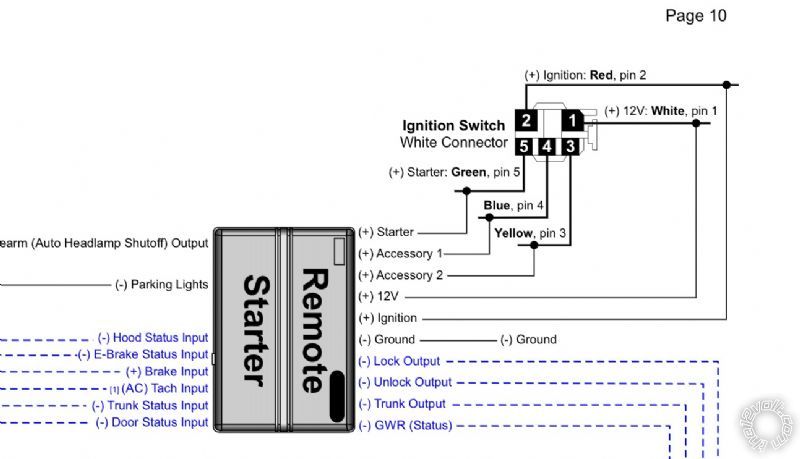
I am preparing to install this system into my 2014 CRV and I am just wanting to make sure I properly understand the accessory wiring. I am just not sure which wires to connect from the viper 10 pin to the vehicle. The install sheet shows accessory 1 and 2 need to be connected. (See pic)
Please forgive my mental disconnect it has been a long work day.
Thanks in advance!
2014 Honda CRV and Viper 5706 -- posted image.
kreg357 
Platinum - Posts: 7,781
Platinum spaceThis member has made a donation to the12volt.com. Click here for more info.spaceThis member has been recognized as an authority in Electrical Theory. Click here for more info.spaceThis member has been recognized as an authority in Mobile Security and Convenience. Click here for more info.spacespace
Joined: January 30, 2009
Location: Pennsylvania, United States
Posted: February 01, 2016 at 7:24 PM / IP Logged Link to Post Post Reply Quote kreg357
Remote Start, 10-pin heavy gauge connector
1 NC No Connection
2 RED / BLACK (+) FUSED 12V ACC/STARTER INPUT White
3 PINK/BLACK (+) FLEX RELAY INPUT 87A  FLEX RELAY    not used
4 PINK/WHITE (+) IGNITION 2 / FLEX RELAY OUTPUT          Yellow    *** Viper Menu 3, Item 8, Opt 2
5 RED (+) FUSED 12V IGNITION 1 INPUT      White
6 GREEN (+) STARTER INPUT (KEY SIDE)    Green
7 VIOLET (+) STARTER OUTPUT (CAR SIDE) Green
8 ORANGE (+) ACCESSORY OUTPUT           Blue
9 RED / WHITE (+) FUSED FLEX RELAY INPUT 87      White
10 PINK (+) IGNITION 1 INPUT/OUTPUT        Red
Soldering is fun!
bt311 
Member - Posts: 5
Member spacespace
Joined: January 21, 2016
Location: Utah, United States
Posted: February 01, 2016 at 7:41 PM / IP Logged Link to Post Post Reply Quote bt311
Kreg thank you for the quick reply!
So that's the part that I need to put my dunce cap on..
Which of those wires do I connect accessory 1 and 2 to?
Thanks again
mscguy 
Copper - Posts: 212
Copper spacespace
Joined: November 28, 2015
Location: British Columbia, Canada
Posted: February 01, 2016 at 7:50 PM / IP Logged Link to Post Post Reply Quote mscguy
He Put that in his reply.
Example...
kreg357 wrote:
8 ORANGE (+) ACCESSORY OUTPUT    Blue
kreg357 
Platinum - Posts: 7,781
Platinum spaceThis member has made a donation to the12volt.com. Click here for more info.spaceThis member has been recognized as an authority in Electrical Theory. Click here for more info.spaceThis member has been recognized as an authority in Mobile Security and Convenience. Click here for more info.spacespace
Joined: January 30, 2009
Location: Pennsylvania, United States
Posted: February 01, 2016 at 7:55 PM / IP Logged Link to Post Post Reply Quote kreg357

The Viper has a thick Orange wire ( H3/8 ) that will be connected to the vehicles Accessory 1 wire ( Blue @ Pin 4 )

The Viper has a Flex ignition output wire ( H3/ 4 Pink/White ) that you will program to Accessory 2 and connect to the
CR-V's Yellow Accessory 2 wire ( Pin 3 ).

It really doesn't matter if you reverse them ( Pink/White to Blue and Orange to Yellow ).  It will accomplish the same thing.

Viper Remote Start, 10-pin heavy gauge connector 2014 Honda CR-V main IGN connector

1 NC No Connection
2 RED / BLACK (+) FUSED 12V ACC/STARTER INPUT White
3 PINK/BLACK (+) FLEX RELAY INPUT 87A  FLEX RELAY     not used
4 PINK/WHITE (+) IGNITION 2 / FLEX RELAY OUTPUT          Yellow    *** Viper Menu 3, Item 8, Opt 2
5 RED (+) FUSED 12V IGNITION 1 INPUT      White
6 GREEN (+) STARTER INPUT (KEY SIDE)    Green
7 VIOLET (+) STARTER OUTPUT (CAR SIDE) Green
8 ORANGE (+) ACCESSORY OUTPUT           Blue
9 RED / WHITE (+) FUSED FLEX RELAY INPUT 87      White
10 PINK (+) IGNITION 1 INPUT/OUTPUT        Red

Soldering is fun!
bt311 
Member - Posts: 5
Member spacespace
Joined: January 21, 2016
Location: Utah, United States
Posted: February 01, 2016 at 10:19 PM / IP Logged Link to Post Post Reply Quote bt311
*flips brain on*
Now I get it! How embarrassing haha! Thank you kindly for your replies!
I got hosed on my 2012 accord install (local stereo shop) so I started looking around online to do it myself. This site has been very helpful!
Again, thanks so much!
bt311 
Member - Posts: 5
Member spacespace
Joined: January 21, 2016
Location: Utah, United States
Posted: February 06, 2016 at 3:45 PM / IP Logged Link to Post Post Reply Quote bt311
So I have started wiring this system and I am curious if I will need to connect anything from the 24 pin connector/harness on the viper 5706 (using DBALL2)
My questions are;
Pin 1: pink/white 200mA ignition 2 output
Pin 13: BLACK/ white neutral safety/parking brake input
Do I need these connected? I was under the assumption that the D2D mode wouldn't require them to be connected.
Thanks!
mscguy 
Copper - Posts: 212
Copper spacespace
Joined: November 28, 2015
Location: British Columbia, Canada
Posted: February 06, 2016 at 4:26 PM / IP Logged Link to Post Post Reply Quote mscguy
bt311 wrote:
My questions are;
Pin 1: pink/white 200mA ignition 2 output
Pin 13: BLACK/ white neutral safety/parking brake input
Do I need these connected? I was under the assumption that the D2D mode wouldn't require them to be connected.
Thanks!
Pink/white = No. Don't confuse this wire with the thick Pink white on the 10 pin heavy gauge connector. The thick one will have to be connected to ignition switch as per Kreg's last post.
BLACK/ white = yes if Automatic. Verify that vehicle will not start in anything but Park or Neutral and then ground the wire. If manual, Has to be connected to ebrake. I'm pretty sure Dball will take care of this for a manual transmission but often this ends up having to be grounded for auto anyway. You can save this for last, and if everything works fine, then then the DBall is taking care of it. If not, ground it.
bt311 
Member - Posts: 5
Member spacespace
Joined: January 21, 2016
Location: Utah, United States
Posted: February 06, 2016 at 7:28 PM / IP Logged Link to Post Post Reply Quote bt311
Awesome thank you so much!

If you wish to post a reply to this topic, you must first login.
If you are not already registered, you must first register.

  Printable version Printable version Post ReplyPost New Topic
You cannot post new topics in this forum
You cannot reply to topics in this forum
You cannot delete your posts in this forum
You cannot edit your posts in this forum
You cannot create polls in this forum
You cannot vote in polls in this forum

  •  
Search the12volt.com
Follow the12volt.com Follow the12volt.com on Facebook
Thursday, March 28, 2024 • Copyright © 1999-2024 the12volt.com, All Rights Reserved Privacy Policy & Use of Cookies
Disclaimer: *All information on this site ( the12volt.com ) is provided "as is" without any warranty of any kind, either expressed or implied, including but not limited to fitness for a particular use. Any user assumes the entire risk as to the accuracy and use of this information. Please verify all wire colors and diagrams before applying any information.

Secured by Sectigo
the12volt.com spacer
Support the12volt.com
Top
the12volt.com spacer