the12volt.com spacer
icon

Door trigger, 2005 Ford F-150


Post ReplyPost New Topic
< Prev Topic Next Topic >
mmatrisch 
Member - Posts: 39
Member spacespace
Joined: April 23, 2016
Location: Illinois, United States
Posted: July 29, 2016 at 5:20 PM / IP Logged Link to Post Post Reply Quote mmatrisch
OK I tried to upload exactly what I wired up into the truck
Matt
mmatrisch 
Member - Posts: 39
Member spacespace
Joined: April 23, 2016
Location: Illinois, United States
Posted: July 29, 2016 at 5:26 PM / IP Logged Link to Post Post Reply Quote mmatrisch
Door trigger, 2005 Ford F-150 - Page 2 -- posted image.Door trigger, 2005 Ford F-150 - Page 2 -- posted image.
Sorry messed up the pictures
Matt
lurch228 
Silver - Posts: 1,338
Silver spacespace
Joined: August 08, 2012
Posted: July 29, 2016 at 6:34 PM / IP Logged Link to Post Post Reply Quote lurch228
Resistor needs to be between the red wire and the diodes in your pic.The yellow wire needs to be hooked to the diodes. The resistor is supposed to limit the 12v input from the red wire into the existing wiring. As you have it wired now you are putting full 12 into vehicle so you can't get to zero ie ground!Door trigger, 2005 Ford F-150 - Page 2 -- posted image.
mmatrisch 
Member - Posts: 39
Member spacespace
Joined: April 23, 2016
Location: Illinois, United States
Posted: July 29, 2016 at 9:55 PM / IP Logged Link to Post Post Reply Quote mmatrisch
ok that did not work either the doors are negative trigger the viper system does not detect the doors again with the way the diaods are placed the only way the door are detected placing the diaod block lines toward the truck wire not toward the the green viper wire
Matt
mmatrisch 
Member - Posts: 39
Member spacespace
Joined: April 23, 2016
Location: Illinois, United States
Posted: July 29, 2016 at 10:07 PM / IP Logged Link to Post Post Reply Quote mmatrisch
Have a question if by ohms law e=I.r 10.10000=.001vdc. If I were to turn the diode block trwrd the viper system and the voltage being in the hundreds of a single volt would that hurt the BCM
Matt
lurch228 
Silver - Posts: 1,338
Silver spacespace
Joined: August 08, 2012
Posted: July 29, 2016 at 10:13 PM / IP Logged Link to Post Post Reply Quote lurch228
Been awhile since doing a Ford alarm install. Looked it up and Yup your right diodes are backwards, everything else should be right.
mmatrisch 
Member - Posts: 39
Member spacespace
Joined: April 23, 2016
Location: Illinois, United States
Posted: July 29, 2016 at 10:17 PM / IP Logged Link to Post Post Reply Quote mmatrisch
OK so to be sure were on the same page I need to turn the diodes around and let that hundredth of a volt go into the BCM I am trying to avoid buying a new BCM if you know what I mean
Matt
lurch228 
Silver - Posts: 1,338
Silver spacespace
Joined: August 08, 2012
Posted: July 29, 2016 at 10:18 PM / IP Logged Link to Post Post Reply Quote lurch228
mmatrisch wrote:
Have a question if by ohms law e=I.r 10.10000=.001vdc. If I were to turn the diode block trwrd the viper system and the voltage being in the hundreds of a single volt would that hurt the BCM
That's why such a high resistor on the (+)12v so the amperage is minimal as to not damage anything. It's amperage that is the killer in 12v systems.Door trigger, 2005 Ford F-150 - Page 2 -- posted image.
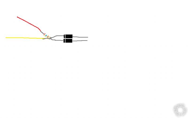
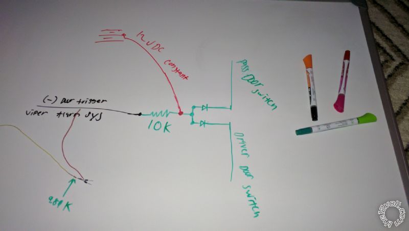
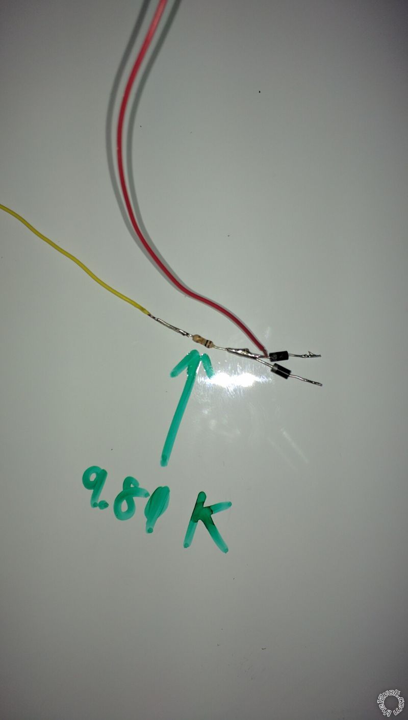
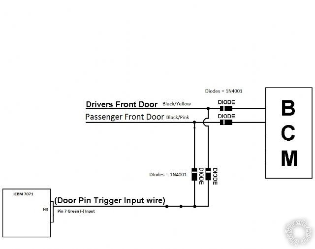
This is the traditional way but the second set of diodes cause the doom light and RAP shutdown to stop working. Deleting the second set of inline Diodes between BCM and door triggers and adding the !@v with resistor elininates this problem.
mmatrisch 
Member - Posts: 39
Member spacespace
Joined: April 23, 2016
Location: Illinois, United States
Posted: July 29, 2016 at 10:26 PM / IP Logged Link to Post Post Reply Quote mmatrisch
Ok that's what I was thinking too but I just wanted the second ok I work with AC voltage bit not DC ok I'm working at the moment I'll keep you posted
Matt
lurch228 
Silver - Posts: 1,338
Silver spacespace
Joined: August 08, 2012
Posted: July 29, 2016 at 10:32 PM / IP Logged Link to Post Post Reply Quote lurch228
No problem, keep me updated.
Page of 4

  Printable version Printable version Post ReplyPost New Topic
You cannot post new topics in this forum
You cannot reply to topics in this forum
You cannot delete your posts in this forum
You cannot edit your posts in this forum
You cannot create polls in this forum
You cannot vote in polls in this forum

  •  
Search the12volt.com
Follow the12volt.com Follow the12volt.com on Facebook
Friday, April 19, 2024 • Copyright © 1999-2024 the12volt.com, All Rights Reserved Privacy Policy & Use of Cookies
Disclaimer: *All information on this site ( the12volt.com ) is provided "as is" without any warranty of any kind, either expressed or implied, including but not limited to fitness for a particular use. Any user assumes the entire risk as to the accuracy and use of this information. Please verify all wire colors and diagrams before applying any information.

Secured by Sectigo
the12volt.com spacer
Support the12volt.com
Top
the12volt.com spacer