the12volt.com spacer
icon

push button start and relays


Post ReplyPost New Topic
< Prev Topic Next Topic >
wmellon 
Member - Posts: 11
Member spacespace
Joined: May 29, 2003
Posted: May 29, 2003 at 10:17 PM / IP Logged  

  Cool.  I have been kicking it around this week and the IC is the only way I can figure it out.  If all else fails, I will do it with an on-on-momentary toggle switch for now.  I guess I can eventually figure it out with some studing.  Any ideas to do it another way or the describe about IC with relays would be great.  Thanks.

soundinstaller 
Member - Posts: 18
Member spacespace
Joined: September 13, 2002
Location: United States
Posted: May 29, 2003 at 10:21 PM / IP Logged  
Did I miss the part of this post string?
What are you trying to accomplish?
wmellon 
Member - Posts: 11
Member spacespace
Joined: May 29, 2003
Posted: May 29, 2003 at 10:24 PM / IP Logged  
  yah, you missed it.  check the first message.  building a true push button start.  no keys with only one switch - push on/ push off.  need a ic with a comparitor to kill the starter when it sees the tach or coil output.
soundinstaller 
Member - Posts: 18
Member spacespace
Joined: September 13, 2002
Location: United States
Posted: May 29, 2003 at 10:42 PM / IP Logged  
ok.
read the others. Tell me why you don't want to use a remote start unit?
Forget the remotes if you don't want to use them, a latched circuit (toggle or latching switch) will work fine if that is what you want to use.
The RS will take care of monitoring your coil, which seems to be your biggest hurdle.
It's cheap, easy and safer.
Getting around the auto shutdown is easy.
Let me know if you want to know how to configure.
bdl666 
Silver - Posts: 330
Silver spacespace
Joined: December 31, 2002
Location: United States
Posted: May 29, 2003 at 11:39 PM / IP Logged  
                      soundinstaller  hit the nail on the head. By using a rs and disabling the auto shut off you can use the same wire to both start and stop the engine. A add-on rs will have a wire that goes to the existing alarm so you can use an extra channel on the alarm to trigger the rs. That will be your on-off switch for the car.
xetmes 
Silver - Posts: 586
Silver spacespace
Joined: May 18, 2003
Posted: May 30, 2003 at 9:16 AM / IP Logged  

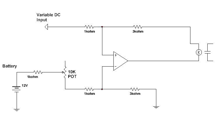
here is a quick idea,it will keep the relay on untill the input gets to 8 V, that is adjustable from 3.2 -> 9.6 V with the 10K pot, you would want to use a high power opamp if driving the relay right off of it unless the relay has a high coil resistance might wanna put a transistor in. Also this really will not do much you still have to add all the other circuitry, but thats my idea based around a difference amplifier. Hope this is of some use to ya.

push button start and relays - Page 2 -- posted image.

wmellon 
Member - Posts: 11
Member spacespace
Joined: May 29, 2003
Posted: May 30, 2003 at 5:49 PM / IP Logged  

  xetmes - that is the idea I am looking for.  Now you have the variable input as a DC current.  The tach is going to be AC; is this going to matter?  Also, by the pot, you look to have put a cap.  Is that right or is the picture missing something?  What value is it, ect.

  soundinstaller - I just prefer to keep the cost down with a $5 IC instead of a $25 remote start.  Either way, outline it for me if you could and suggest a rm maybe.  I figure you don't connect the switch for the brake kill, don't set the timer and hard wire the rf reciever to the push button to simulate a remote input.  Question is, will you piss off the rs gem with a constant input from the bridged push button switch?  Remember, there will be a constant input, not just a small fixed one like a remote pulse.  Maybe/Hopefully I missed something.  Like I said, outline it for me if you could so I can figure it out.  Thanks.

xetmes 
Silver - Posts: 586
Silver spacespace
Joined: May 18, 2003
Posted: May 30, 2003 at 7:06 PM / IP Logged  

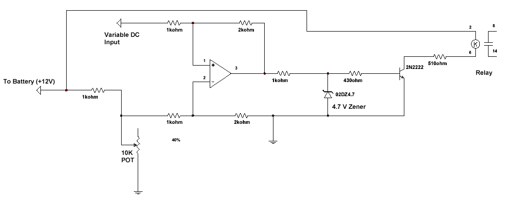
ok i did i little more thinking, note this may not work at all, it would in theory and does in simulation, but that does not mean it will in real life, but just my ideas...

This will keep the relay closed from an input of 0V -> 8V, at 8V the relay will open and the connection lost.

push button start and relays - Page 2 -- posted image.

wmellon 
Member - Posts: 11
Member spacespace
Joined: May 29, 2003
Posted: May 30, 2003 at 8:04 PM / IP Logged  
  Okay, my symbol knowlegde is a bit rusty, so just a few questions.  Zener - diode right?  Okay, dumb, but what is the triangle.  I for the life of me can not remember what the hell it means.  I'll throw it together on my test board and try it out.  Better there than burning out my car electrical system!  Thanks.
xetmes 
Silver - Posts: 586
Silver spacespace
Joined: May 18, 2003
Posted: May 30, 2003 at 8:23 PM / IP Logged  
yea i would HIGHLY recommend trying it out on a breadboard first, the triangle in the middle is a just an opamp, no special kind, just any normal opamp you get your hands on. yea thats a 4.7V zener, you could probably use a 5.1V also if thats easier, its just to limit current to the transistor. Good luck, let me know how it goes.. push button start and relays - Page 2 -- posted image.
Page of 3

  Printable version Printable version Post ReplyPost New Topic
You cannot post new topics in this forum
You cannot reply to topics in this forum
You cannot delete your posts in this forum
You cannot edit your posts in this forum
You cannot create polls in this forum
You cannot vote in polls in this forum

  •  
Search the12volt.com
Follow the12volt.com Follow the12volt.com on Facebook
Thursday, May 9, 2024 • Copyright © 1999-2024 the12volt.com, All Rights Reserved Privacy Policy & Use of Cookies
Disclaimer: *All information on this site ( the12volt.com ) is provided "as is" without any warranty of any kind, either expressed or implied, including but not limited to fitness for a particular use. Any user assumes the entire risk as to the accuracy and use of this information. Please verify all wire colors and diagrams before applying any information.

Secured by Sectigo
the12volt.com spacer
Support the12volt.com
Top
the12volt.com spacer