This is a basic remote start with keyless entry install Pictorial on a 2010 Ford F150. The 2009 and 2010 models should be identical.
This FISO ( sorry, old blonde joke

) was a entry level XL model with a 4.6L V-8, Automatic Transmission, Factory Remote Keyless Entry
and no Factory Alarm system.
Notes on these F150's :
Ford was in the process of going to 80 bit transponder systems. Some trucks might have the HA or SA marked keys. All of the ones
I have done still had the older 40 bit encryption so bypass modules like the Directed 1100F, PKALL, Key-Override-ALL, ADS TBSL KO
and others work on these trucks. However, you still need two unique ( non-clone ) keys to program the bypass module to the truck.
Trucks with factory RKE have Type B door lock systems, while trucks without RKE have Type C ( 5 wire REV ) systems. The wires
at the BCM are the same color and location so testing is necessary. If your truck has Type C, use a Directed 451M door lock module
properly connected to the wires shown below.
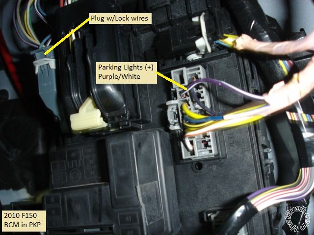
Parking Lights - while you might think you found a (-) Parking Light wire at the Headlight switch, don't use it unless you add a
relay and follow DEI Tech Tip 1096. The safe and easy way is to use the (+) Parking Light wire shown.
These trucks have "one-touch starting" where you can just turn the ignition key to START and release it. The ECM will crank and
start the engine. Running the R/S unit in Tach Mode is not mandatory, Tachless or Fixed crank will work fine.
The ignition wires are 18 gauge ( thin ). Most R/S systems have 12 gauge ignition wires. For a cleaner install and easier soldering
you can cut these wires short and connect quality 18 gauge wires for the run to the ignition switch harness.
For this install an Ultra Start U1272 was selected. Some other good choices currently available are the Avital 4103LX, Viper 4105V,
Compustar CS800-s and the Prestige APS57E. While you could go with a one button system, this truck has separate key and FOB's.
The factory FOB's are 6 years old and getting tired so a 4 button R/S system is a bonus to the customer.
The ADS TB bypass module was used for this install. The original plan was to use a Fortin Key-Override-ALL but the customer only
brought one working key. The DIYer typically uses bypass modules that come pre-loaded with the correct firmware while professional
installer has more options. The ADS TB must be flashed with the ADS TB FM2 firmware using a special USB cable and then can be
programmed to the truck with just one key using the KLON utility.
For the DIYer, the below wiring will use the iDatalink ADS TBSL KO bypass module, which comes pre-loaded and is ready to use.
U1272 wiring :
6 Pin Ignition Harness
1 Yellow (+) Starter Output Blue/White (+) @ IGNITION SWITCH HARNESS
2 Green (+) Accessory Output PURPLE / Green (+) @ IGNITION SWITCH HARNESS
3 Red (+) +12V constant \ Combine both Red wires, fuse down to 20 Amps and connect
4 Red (+) +12V constant / to SJB Black 1 Pin plug, Red wire or vehicle battery.
5 White (+) Flex Relay Output Not Used
6 Blue (+) Ignition Output WHITE/ Orange (+) IGNITION SWITCH HARNESS ( plus Pink wire from ADS TBSL KO )
2 Pin Harness
Black (-) Main Chassis Ground Chassis Ground @ Factory Bolt
White Selectable Parking Light Output PURPLE / White @ SJC 13 Pin Plug E * Set to (+)
9 Pin Harness
1 Yellow (-) Rearm Output Not Used
2 Brown (-) Disarm Output Not Used
3 Black (-) AUX1 Output Not Used
4 RED / White (-) Trunk Release Not Used
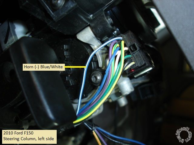
5 WHITE/ Blue (-) Horn Output Blue/White @ Steering Column
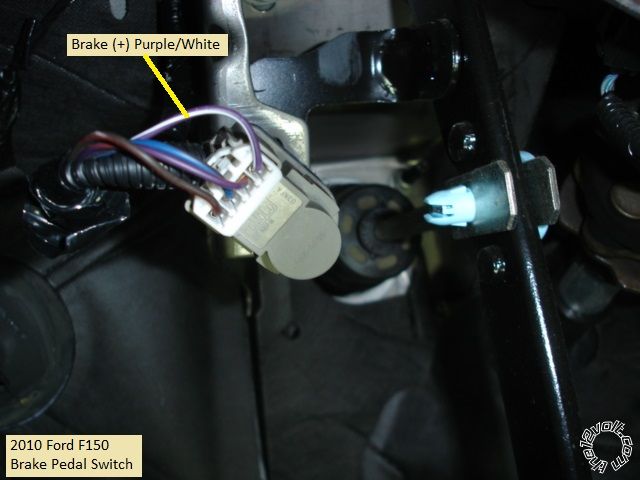
6 Pink (+) Brake Input PURPLE / White (+) @ SWITCH ABOVE BRAKE PEDAL
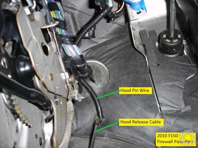
7 GREEN / WHITE (-) Hood Pin Input to mercury switch mounted to hood hinge bolt
8 Blue/White (AC) Tach Input Not Used
9 Blue (+/-) Glow Plug/WTS/Trigger Input Not Used
Lock Harness
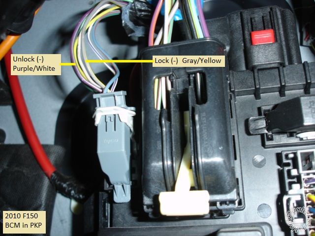
Green (-) Lock Gray / YELLOW @ SJB, 26 Pin Plug C in PKP
Blue (-) Unlock PURPLE / Gray @ SJB, 26 Pin Plug C in PKP
The thick Red power wire, the two lock wires and the Parking Light wire must be lengthened to make to run over to the SJB in the PKP.
Connect the D2D harness supplied in the ADS TBSL KO package between the U1272 and the ADS TBSL KO.
ADS TBSL KO wires
Pink wire to the U1272 thick Blue Ignition wire
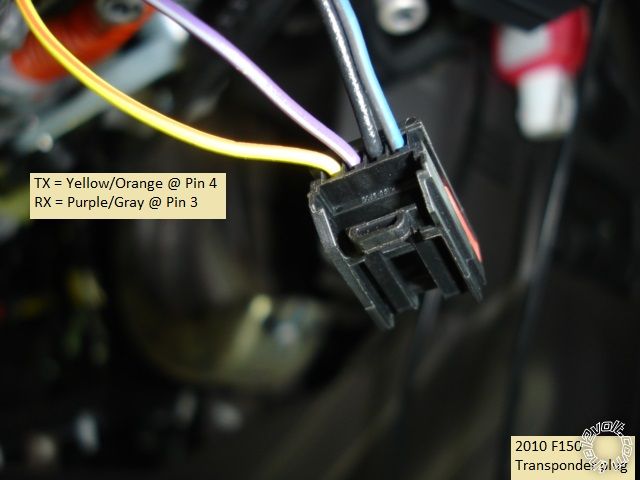
Gray/Red wire to Violet/Gray @ transponder plug
GREEN/ Red to Yellow/Orange @ transponder plug
Disassembly :
Remove the PKP cover panel by pulling in on the front edge.
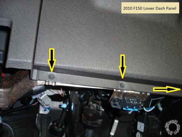
Remove the lower dash panel beneath the steering column by removing the three 7mm screws shown in the photo below and pulling
it straight away. There are two clips in the upper corners.
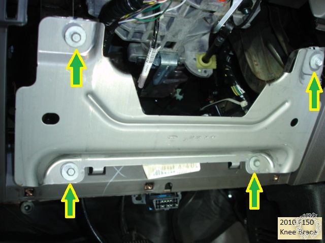
Remove the knee brace by removing the four 8mm bolts indicated in the picture below.
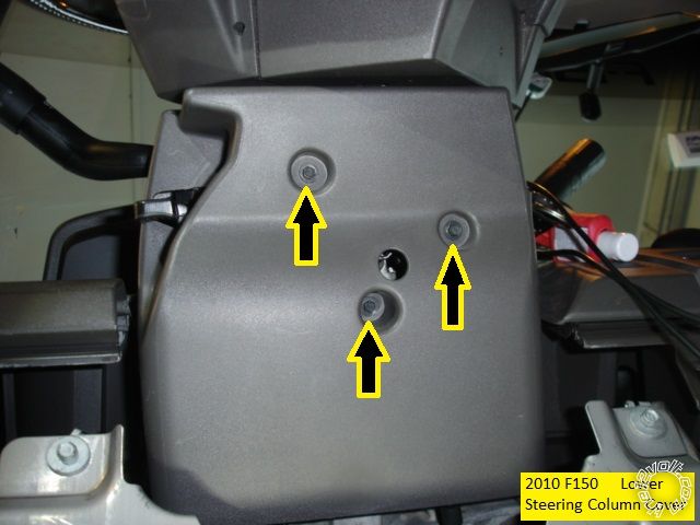
Next remove the three 5.5mm screws marked in the photo below, then carefully separate the lower steering column cover from the upper
section and place it aside.
All of the necessary wires are now exposed. Here are photos of the wires used :
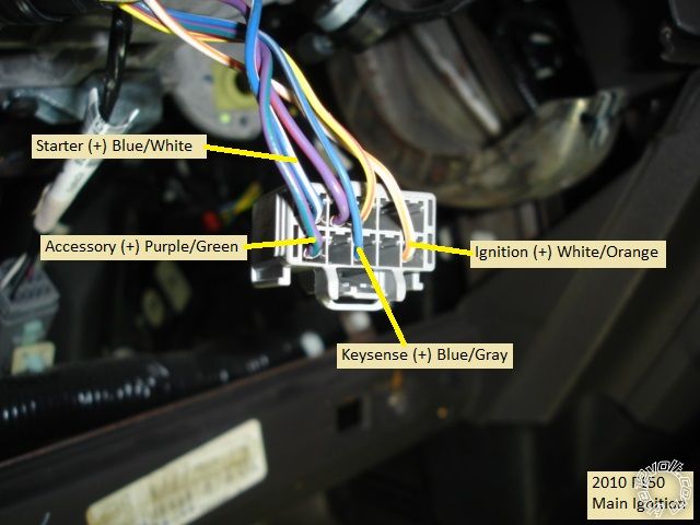
On the left side of the Steering column is the main ignition connector ( hidden behind the tilt lever ). Here is the main ignition
connector, unplugged, with the wires marked. ( Keysense is shown but not needed.)
Below is a picture of the steering column clock spring connector ( left side of column, just above the ignition plug and closer to the
steering wheel ) with the Horn wire indicated.
On the right side of the steering column, by the ignition key cylinder, is the 4 pin transponder plug. This is a photo of this
connector, unplugged.
At the top of the Brake pedal assy is the Brake pedal switch and plug. Below is a photo with the Brake wire marked.
The remaining wires are found at the SJB in the PKP. The Lock and Unlock wires ( w/RKE ) are in the top left plug and shown below :
The (+) Parking Light wire is in a connector on the right side of the SJB and pictured below.
Firewall pass-through for the Hood pin wire can be found at the Hood Release cable grommet. Photo below.
Chassis ground can be found at the bolts in the upper DKP area. Remove the side dash panel to run the antenna harness and
make this ground connection ( using a soldered-on terminal lug ).
There are other places to catch most of these wires. All of them can be had at the SJB but it's easier ( for me ) to work under the drivers
side dash area.... There is a thick Red wire in the DPK bundle that can be used as the R/S +12V constant power source.
Remember to set the ADS TBSL KO Installation Mode to Data, one blink, and lock it in prior to vehicle programming.
As always, test all wires with a Digital Multi Meter before making your quality soldered connections.
Soldering is fun!


 Topic Closed)


 Printable version


