


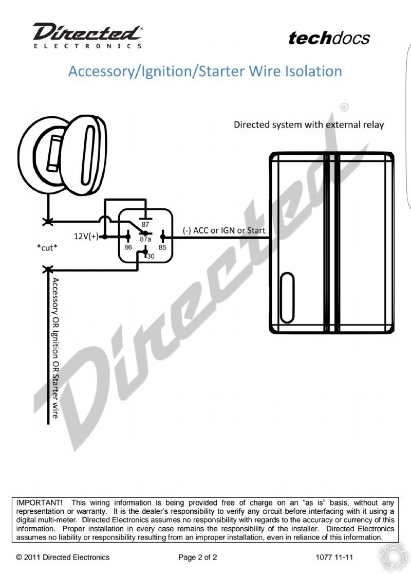
 NOTE *2 THIS VEHICLES ACCESSORY #1 WIRE MUST BE ISOLATED FOR REMOTE STARTING AND REQUIRES AN EXTRA RELAY PART #775, TO PREVENT THE VEHICLE FROM OVER CRANKING WITH THE IGNITION KEY, TO CONNECT, See DIAGRAM
Nissan Accessory Isolation Circuit http://diagrams.marktoonen.nl/DOWNLOADS/14301_ALTIMA_NISSAN%20ACCESSORY%20ISOLATION%20CIRCUIT.pdf
Encore E9 Installation manual
http://encoreautomotivesystems.com/content/pdf/E9_install_manual.pdf
Car Wiring Code
http://www.bulldogsecurity.com/bdnew/vehiclewiringdiagrams.aspx
http://www.alarmsellout.com/support/diagrams/vehicle/NISSAN%20ALTIMA%201993-2005.pdf
http://www.S P A M.com/1998-nissan-altima-remote-start-system-wiring/
http://www.commandocaralarms.com/wiring/1998-2001/nissan/altima/1607.html
Thanks in advance
NOTE *2 THIS VEHICLES ACCESSORY #1 WIRE MUST BE ISOLATED FOR REMOTE STARTING AND REQUIRES AN EXTRA RELAY PART #775, TO PREVENT THE VEHICLE FROM OVER CRANKING WITH THE IGNITION KEY, TO CONNECT, See DIAGRAM
Nissan Accessory Isolation Circuit http://diagrams.marktoonen.nl/DOWNLOADS/14301_ALTIMA_NISSAN%20ACCESSORY%20ISOLATION%20CIRCUIT.pdf
Encore E9 Installation manual
http://encoreautomotivesystems.com/content/pdf/E9_install_manual.pdf
Car Wiring Code
http://www.bulldogsecurity.com/bdnew/vehiclewiringdiagrams.aspx
http://www.alarmsellout.com/support/diagrams/vehicle/NISSAN%20ALTIMA%201993-2005.pdf
http://www.S P A M.com/1998-nissan-altima-remote-start-system-wiring/
http://www.commandocaralarms.com/wiring/1998-2001/nissan/altima/1607.html
Thanks in advance


 Thanks for the reply!
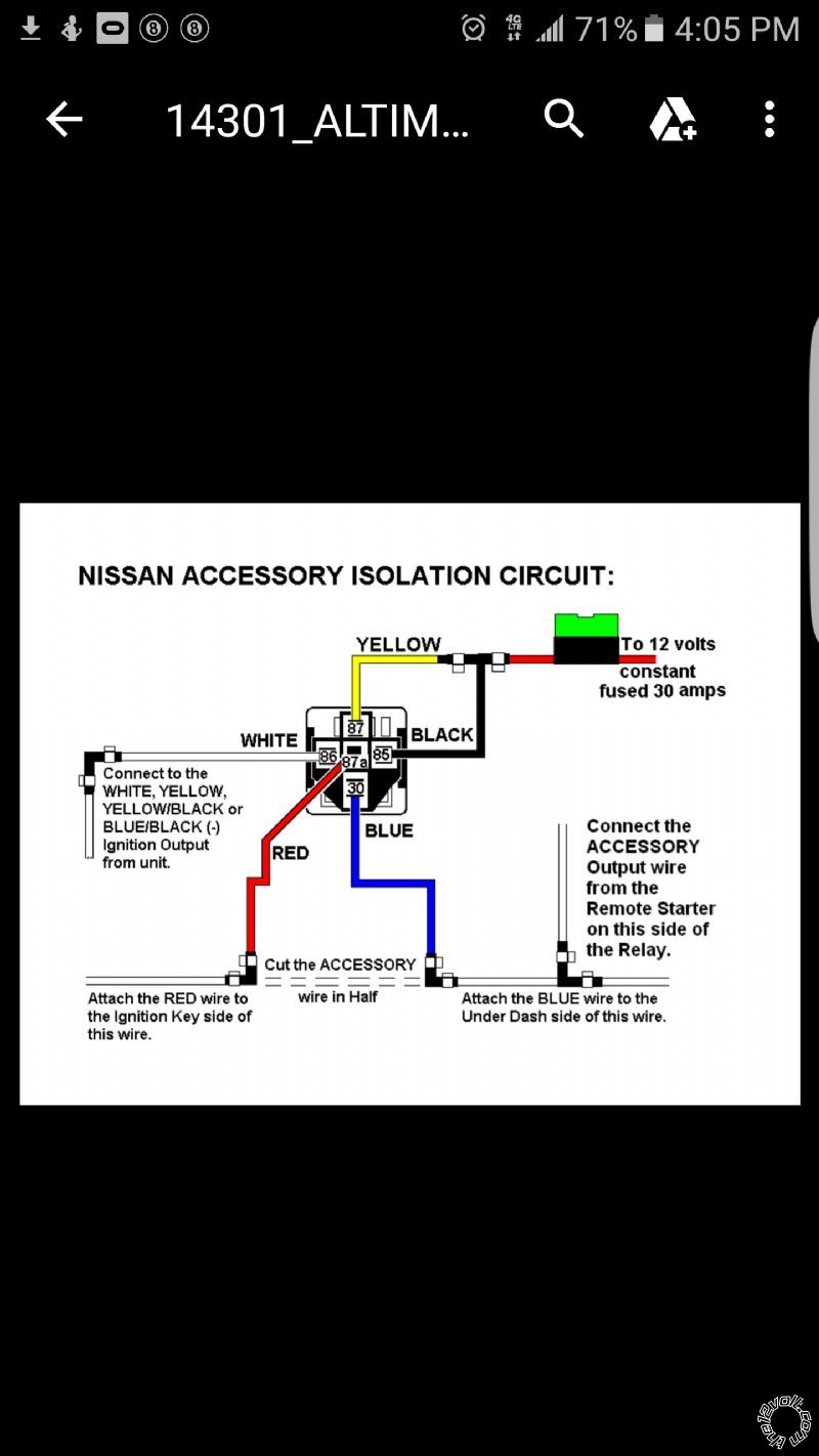
If I use this accessory isolation diagram
Pin 86 and 87 are 12v constants which i will fuse at 30 amps
Pin 87a is accessory wire from ignition side
Pin 30 is accessory wire from car side
Pin 85 is (-) accessory...since my accessory output is (+) on the remote start should I use the ground when running output (GWR)?
Does this look right? If so...what do I do with the accessory 1 output
on the remote start?
Also I believe the car has a accessory 2...should I connect that to the accessory 2 output on the remote start? No isolation needed?
Ive just went to the installtion manual and noticed something. On the remote start I notice the accessory 2 is a (-) output
Let's say if I use the (-) accessory 2 output on the relay instead of the ground when running wire... which output on the remote start will I connect the accessory 2 to the car?
Am I over thinking this?
Looking foward hearing from you guys
Thanks for the reply!
If I use this accessory isolation diagram
Pin 86 and 87 are 12v constants which i will fuse at 30 amps
Pin 87a is accessory wire from ignition side
Pin 30 is accessory wire from car side
Pin 85 is (-) accessory...since my accessory output is (+) on the remote start should I use the ground when running output (GWR)?
Does this look right? If so...what do I do with the accessory 1 output
on the remote start?
Also I believe the car has a accessory 2...should I connect that to the accessory 2 output on the remote start? No isolation needed?
Ive just went to the installtion manual and noticed something. On the remote start I notice the accessory 2 is a (-) output
Let's say if I use the (-) accessory 2 output on the relay instead of the ground when running wire... which output on the remote start will I connect the accessory 2 to the car?
Am I over thinking this?
Looking foward hearing from you guys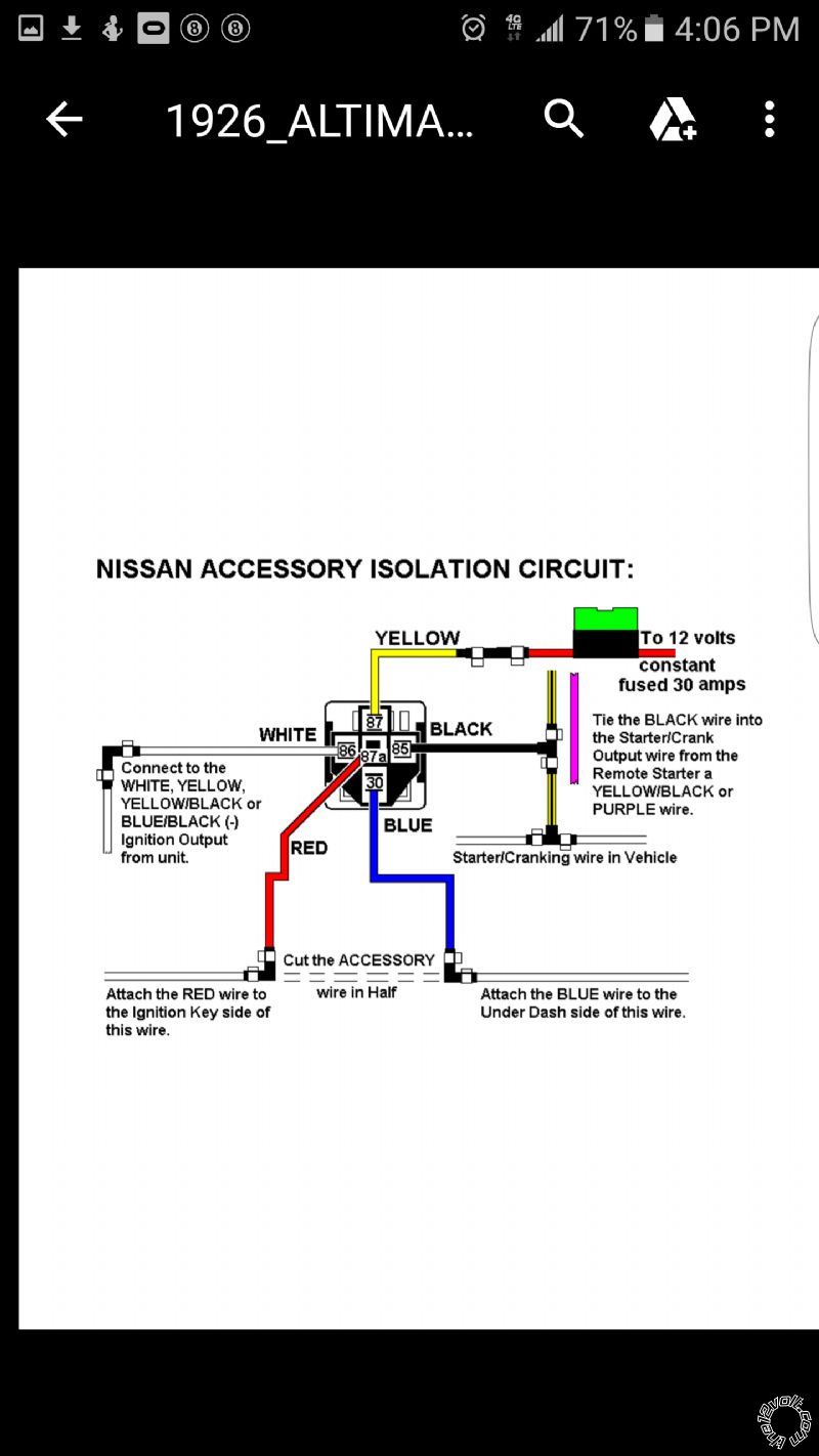
If you wish to post a reply to this topic, you must first login.
If you are not already registered, you must first register.
 Printable version


| You cannot post new topics in this forum You cannot reply to topics in this forum You cannot delete your posts in this forum You cannot edit your posts in this forum You cannot create polls in this forum You cannot vote in polls in this forum |

| Search the12volt.com |
Follow the12volt.com 
Saturday, May 16, 2026 • Copyright © 1999-2026 the12volt.com, All Rights Reserved • Privacy Policy & Use of Cookies

Saturday, May 16, 2026 • Copyright © 1999-2026 the12volt.com, All Rights Reserved • Privacy Policy & Use of Cookies
Disclaimer:
*All information on this site ( the12volt.com ) is provided "as is" without any warranty of any kind, either expressed or implied, including but not limited to fitness for a particular use. Any user assumes the entire risk as to the accuracy and use of this information. Please
verify all wire colors and diagrams before applying any information.
