


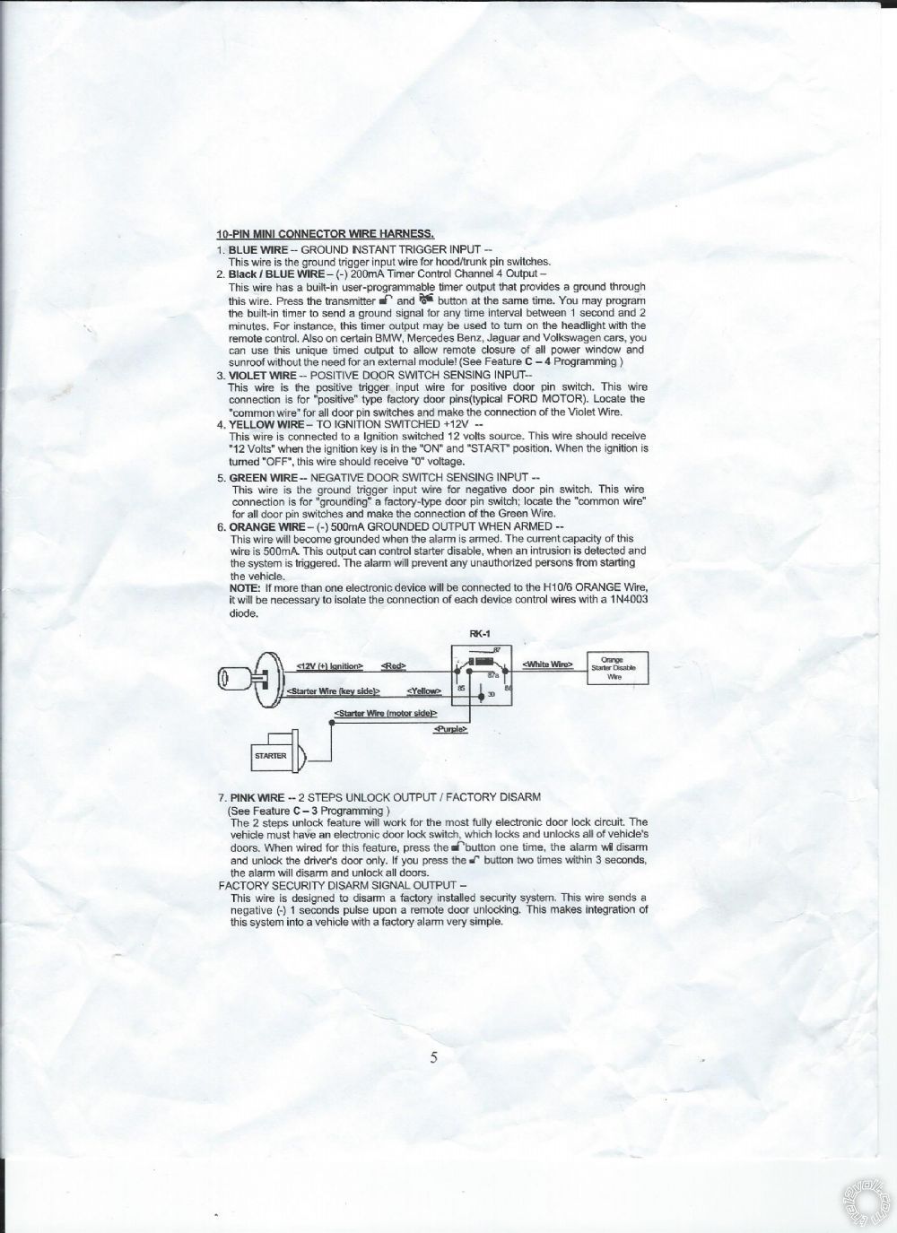
 In this image autopage has an "orange wire negative when armed" to energize the coil in the relay.(86) Then they have 12 volts from ignition key. They put the starter or {mopar starter relay in my case} on the (87a) and then the key "yellow" wire on the (30) terminal. When "armed" it is supposed to disable the key's connection to the relay starter motor. This is just plain stupid cause when the coil is energized it will connect terminal (30) to (87a).Turning the key while its armed is only going to connect the starter to the key. The whole point is to disconnect the starter when armed if you turn the key.Useless instructions.
Nothing is "disabled".
In this image autopage has an "orange wire negative when armed" to energize the coil in the relay.(86) Then they have 12 volts from ignition key. They put the starter or {mopar starter relay in my case} on the (87a) and then the key "yellow" wire on the (30) terminal. When "armed" it is supposed to disable the key's connection to the relay starter motor. This is just plain stupid cause when the coil is energized it will connect terminal (30) to (87a).Turning the key while its armed is only going to connect the starter to the key. The whole point is to disconnect the starter when armed if you turn the key.Useless instructions.
Nothing is "disabled".
If you wish to post a reply to this topic, you must first login.
If you are not already registered, you must first register.
 Printable version


| You cannot post new topics in this forum You cannot reply to topics in this forum You cannot delete your posts in this forum You cannot edit your posts in this forum You cannot create polls in this forum You cannot vote in polls in this forum |

| Search the12volt.com |
Follow the12volt.com 
Friday, July 26, 2024 • Copyright © 1999-2024 the12volt.com, All Rights Reserved • Privacy Policy & Use of Cookies

Friday, July 26, 2024 • Copyright © 1999-2024 the12volt.com, All Rights Reserved • Privacy Policy & Use of Cookies
Disclaimer:
*All information on this site ( the12volt.com ) is provided "as is" without any warranty of any kind, either expressed or implied, including but not limited to fitness for a particular use. Any user assumes the entire risk as to the accuracy and use of this information. Please
verify all wire colors and diagrams before applying any information.
