the12volt.com spacer
icon

01 Honda S2000, CM7000 Evo-all


Post ReplyPost New Topic
< Prev Topic Next Topic >
jdmegcoupe 
Copper - Posts: 80
Copper spaceThis member has made a donation to the12volt.com. Click here for more info.spacespace
Joined: October 15, 2003
Location: Massachusetts, United States
Posted: July 31, 2017 at 7:06 PM / IP Logged Link to Post Post Reply Quote jdmegcoupe
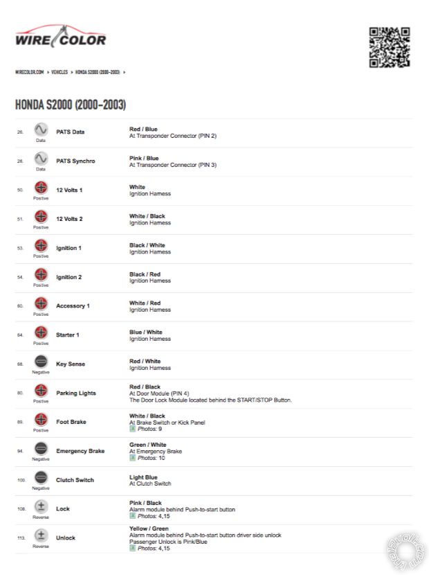
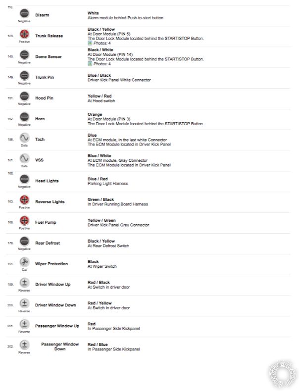
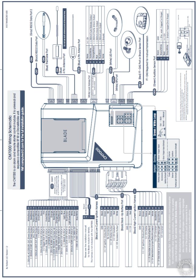
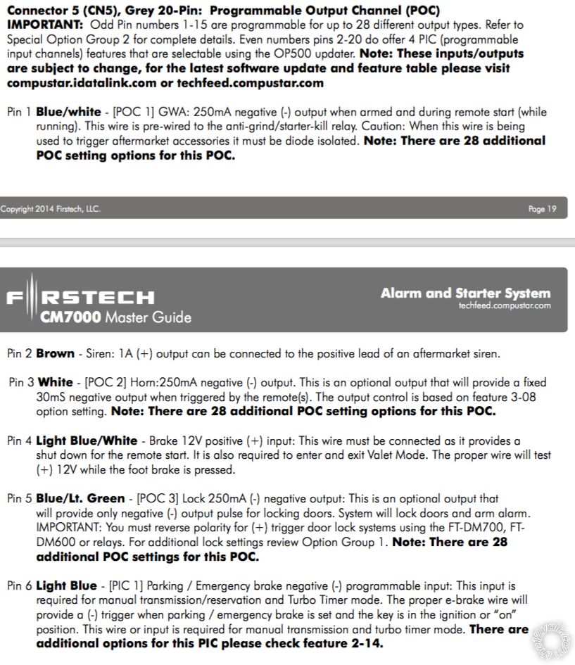
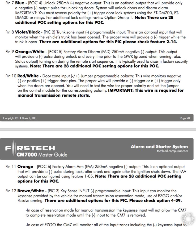
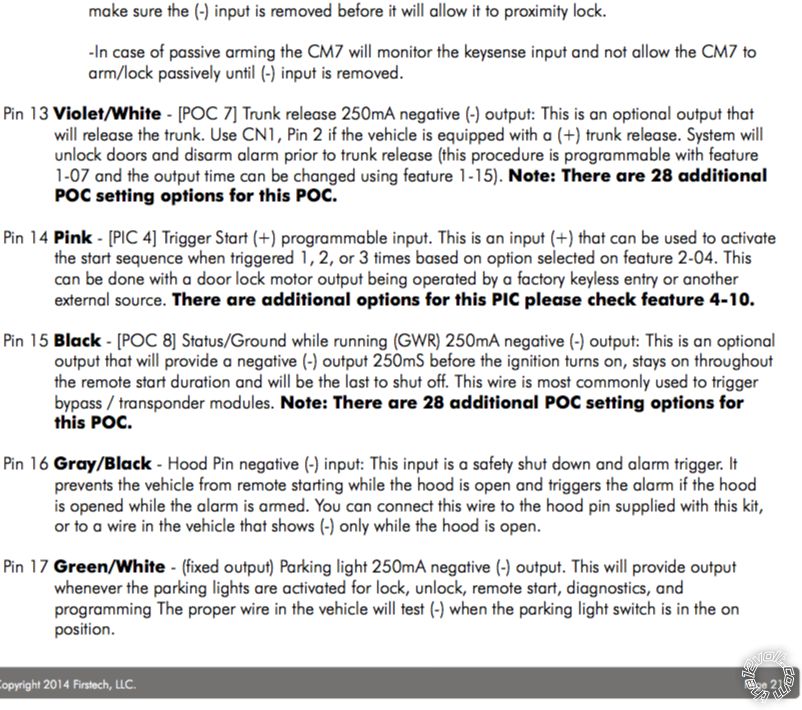
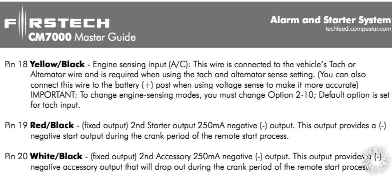
Hello again, for some reason I am having trouble understanding the wiring diagram of the cm7000 I have installed this before but for the life of me I cant seem to comprehend this now. Maybe its due to my PTSD... well the car is a 2001 Honda S2000 I have a wire color wiring diagram for the s2000 the issue I am having is with CN5 harness. I know where to CN5 PIN 1,2,3,4,6,8,10,16 are to be connected, my question is for CN5 PIN 5,7,9,11,13,14,15,17,18,19,20
Thanks and I hope the images i uploaded help
01 Honda S2000, CM7000 Evo-all -- posted image.
jdmegcoupe 
Copper - Posts: 80
Copper spaceThis member has made a donation to the12volt.com. Click here for more info.spacespace
Joined: October 15, 2003
Location: Massachusetts, United States
Posted: August 03, 2017 at 1:44 PM / IP Logged Link to Post Post Reply Quote jdmegcoupe
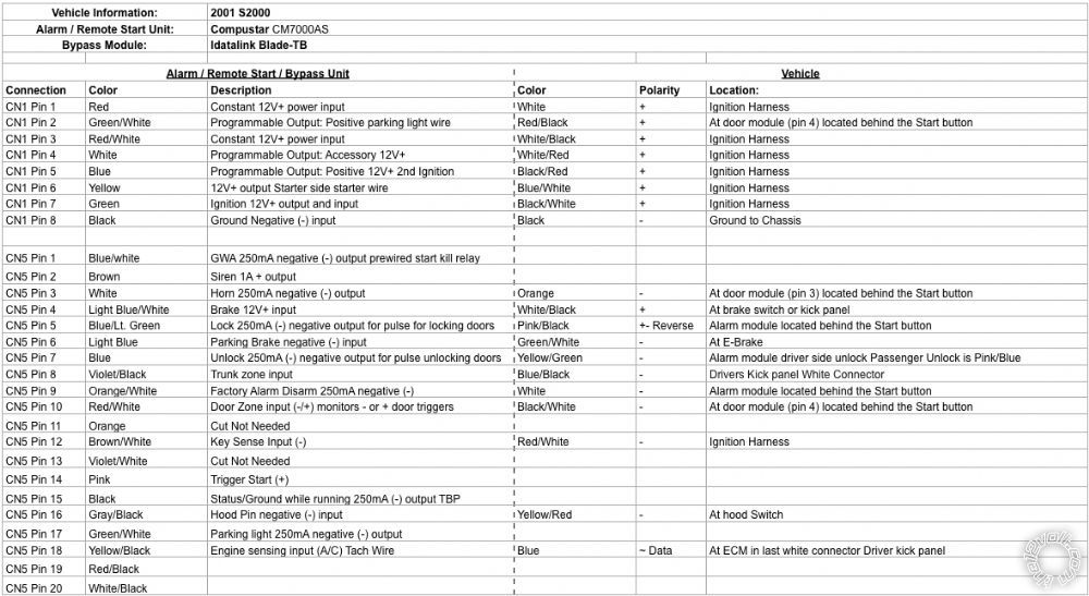
Okay can someone tell me if this is correct?
01 Honda S2000, CM7000 Evo-all -- posted image.
kreg357 
Platinum - Posts: 7,781
Platinum spaceThis member has made a donation to the12volt.com. Click here for more info.spaceThis member has been recognized as an authority in Electrical Theory. Click here for more info.spaceThis member has been recognized as an authority in Mobile Security and Convenience. Click here for more info.spacespace
Joined: January 30, 2009
Location: Pennsylvania, United States
Posted: August 04, 2017 at 4:23 AM / IP Logged Link to Post Post Reply Quote kreg357
Haven't done a 2001 S2000 but...
Looks good on the ignition wires.
Noticed a few issues with the power door locks. They are listed as Type C Reverse. As such you can't make a direct connection using the CM7000 (-) door lock outputs. You will need a few relays or a Directed 451M Door Lock Module ( < $9 ). There is a 451M Install Guide in the Downloads section. With the 451M module cut the 3 Pin connector and hardwire to the CM7000 and then follow Wiring Diagram C.
The Keysense connection might not be required.
Verify that the CM7000 will alarm when either door is opened. The Door Trigger you are using is listed as the Domelight so you should be OK.
The big issue will be the Clutch Interlock. With your manual transmission S2000, you need to depress the clutch pedal to engage the starter motor. The WireColor chart lists this wire as (-). You have a few options. I like to use a (-) Starter signal for Honda's. Being as you are not using POC #1, CN5 Pin 1, I would program it as (-) 2nd Starter, Opt 2, and use it.
Additional thoughts :
You are not using the CM7000 to pop the Trunk. The S2000 needs a (+) signal for this. You could get a SPDT relay and use the (-) Trunk output to control it or you could re-program the CN1 Pin 2 wire from (+) Parking Light to (+) Trunk and use that wire. This change would also require you to use CN5 Pin 17 for the Parking Lights, now going to the (-) Parking Light wire at the Headlight switch.
I'm assuming that you have the Blade TB programmed with TB-HA firmware and will make those required connection for the transponder bypass.
Soldering is fun!

If you wish to post a reply to this topic, you must first login.
If you are not already registered, you must first register.

  Printable version Printable version Post ReplyPost New Topic
You cannot post new topics in this forum
You cannot reply to topics in this forum
You cannot delete your posts in this forum
You cannot edit your posts in this forum
You cannot create polls in this forum
You cannot vote in polls in this forum

  •  
Search the12volt.com
Follow the12volt.com Follow the12volt.com on Facebook
Friday, March 29, 2024 • Copyright © 1999-2024 the12volt.com, All Rights Reserved Privacy Policy & Use of Cookies
Disclaimer: *All information on this site ( the12volt.com ) is provided "as is" without any warranty of any kind, either expressed or implied, including but not limited to fitness for a particular use. Any user assumes the entire risk as to the accuracy and use of this information. Please verify all wire colors and diagrams before applying any information.

Secured by Sectigo
the12volt.com spacer
Support the12volt.com
Top
the12volt.com spacer