the12volt.com spacer
icon

auto headlights-remote start


Post ReplyPost New Topic
< Prev Topic Next Topic >
jonb2 
Copper - Posts: 59
Copper spacespace
Joined: January 07, 2008
Location: California, United States
Posted: November 13, 2017 at 3:40 PM / IP Logged Link to Post Post Reply Quote jonb2
Hi all. 2007 Toyota 4runner and I just added Avital remote start. Vehicle has auto headlights. Did some research and it appears I need to install a relay so that the headlights automatically turn off when the remote starter shuts down. Unless you physically open the driver door, the headlights will stay on forever after remote shutdown. Can you tell me how to wire such a relay?
thanks!
kreg357 
Platinum - Posts: 7,783
Platinum spaceThis member has made a donation to the12volt.com. Click here for more info.spaceThis member has been recognized as an authority in Electrical Theory. Click here for more info.spaceThis member has been recognized as an authority in Mobile Security and Convenience. Click here for more info.spacespace
Joined: January 30, 2009
Location: Pennsylvania, United States
Posted: November 13, 2017 at 7:13 PM / IP Logged Link to Post Post Reply Quote kreg357
Well, you have a few choices. You can pulse the door trigger wire after a R/S shutdown or you can open
the Auto-Headlights wire during a R/S. The problem comes in finding an Avital output that can do what
you want, when you want it. Sometimes the (-) Rearm output connected to a typical N.O. Door Trigger
wire will do the trick. Sometimes you might have to "strengthen" that Rearm signal with a relay. The
way I like to do it is with a relay that is triggered by GWR or Status Output and opens the AutoHeadlight
wire at the steering wheel headlight connector. On most Toyotas there is a (-) AutoHeadlight wire at that
connector. It is usually right next to the (-) Parking Light wire. Test for this wire and then wire up a relay
using the Avital 2nd Status Output wire like so :
Relay Pin 85 to Avital 2nd Status Output
Relay Pin 86 to +12V constant
Relay Pin 87a to one side of cut AutoHeadlight wire
Relay Pin 30 to the other side of the cut AutoHeadlight wire
What happens :
When a R/S is called for, the 2nd Status output comes on a second or two before the Avital starts turning
on the ignition wires. The 2nd Status signal energizes the relay which opens the AutoHeadlight signal
coming from the switch. If the headlight control switch was left at Auto, the (-) signal would not be seen
or acted upon by the BCM, like it was never there, which in turn would prevent the headlights left on
situation all together. At all other times, the headlight switch operates normally.
Soldering is fun!
jonb2 
Copper - Posts: 59
Copper spacespace
Joined: January 07, 2008
Location: California, United States
Posted: November 13, 2017 at 11:41 PM / IP Logged Link to Post Post Reply Quote jonb2
great thank you for such a detailed explanation. I also located the automatic light control sensor. Can I do something similar using the wires connected to that sensor? Rather than cutting the auto headlights wire could I cut one of the wires on the light control sensor and accomplish the same thing?
Just a little nervous about cutting a main wire that controls the headlight in case the relay goes bad or the connections somehow work loose.
thanks again.
kreg357 
Platinum - Posts: 7,783
Platinum spaceThis member has made a donation to the12volt.com. Click here for more info.spaceThis member has been recognized as an authority in Electrical Theory. Click here for more info.spaceThis member has been recognized as an authority in Mobile Security and Convenience. Click here for more info.spacespace
Joined: January 30, 2009
Location: Pennsylvania, United States
Posted: November 14, 2017 at 7:22 AM / IP Logged Link to Post Post Reply Quote kreg357
Never tried it with the actual light sensor. It would have to be some kind of input to a logic circuit to know it's dark enough and that the AutoHeadlight function is ON. Personally, finding the AutoHeadlight wire at the headlight switch is much easier and more direct. Connections are not an issue there, where you can solder and use heat shrink tube. Relay failures are very rare, especially considering a simple ground signal is passed through Pins 87a to 30 in a N.C. situation. Most relays have a better than 100,000 operation cycles MTBF rating. I might agree with you if you were adding an Anti-Grind relay. That is a high current (+) signal and more critical to vehicle operation, but again proper components, soldered connections and quality insulation negates issues.
Soldering is fun!
jonb2 
Copper - Posts: 59
Copper spacespace
Joined: January 07, 2008
Location: California, United States
Posted: November 15, 2017 at 11:39 AM / IP Logged Link to Post Post Reply Quote jonb2
Great thanks. I have wiring diagrams but not sure exactly which wire or wire color I should be using. Can you advise? thank you.
kreg357 
Platinum - Posts: 7,783
Platinum spaceThis member has made a donation to the12volt.com. Click here for more info.spaceThis member has been recognized as an authority in Electrical Theory. Click here for more info.spaceThis member has been recognized as an authority in Mobile Security and Convenience. Click here for more info.spacespace
Joined: January 30, 2009
Location: Pennsylvania, United States
Posted: November 15, 2017 at 7:23 PM / IP Logged Link to Post Post Reply Quote kreg357
Sorry, I don't have any info on your 2007 4Runner. Here is a photo from a 2014 Tundra :
auto headlights-remote start -- posted image.
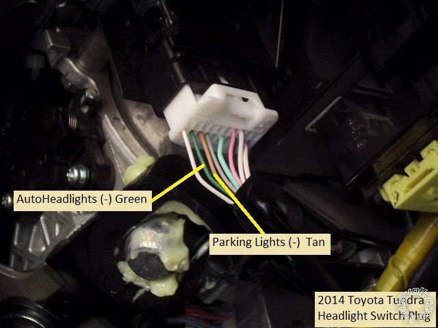
The wires are marked. Your connector might be different and your (-) Parking Light wire is Green instead of Tan.
Anyway, here is the test. Using a Digital Multi Meter set to 20 Volts DC, connect the Red test lead to +12V
constant and the Black Test lead to the suspect wire ( probably next to the Green (-) Parking Light wire ). With
the switch in the OFF position, you will see 0V. When you set the switch to AUTO, the DMM should go to +12V. After
this test finds the wire, the next test would be to cut the wire and see if the AutoHeadlight function still works.
Finally, after all the testing, wire up your relay to the cut ends
of the AutoHeadlight wire as shown above.
Soldering is fun!
jonb2 
Copper - Posts: 59
Copper spacespace
Joined: January 07, 2008
Location: California, United States
Posted: November 16, 2017 at 3:09 PM / IP Logged Link to Post Post Reply Quote jonb2
Awesome thank you again for such detailed explanations and a nice walkthrough of the procedure. I will check it out this weekend. In the meantime I did find a wiring diagram for my vehicle. I was wondering if I could cut the green/orange wire marked as "A" and accomplish the same thing??
auto headlights-remote start -- posted image.
kreg357 
Platinum - Posts: 7,783
Platinum spaceThis member has made a donation to the12volt.com. Click here for more info.spaceThis member has been recognized as an authority in Electrical Theory. Click here for more info.spaceThis member has been recognized as an authority in Mobile Security and Convenience. Click here for more info.spacespace
Joined: January 30, 2009
Location: Pennsylvania, United States
Posted: November 16, 2017 at 5:30 PM / IP Logged Link to Post Post Reply Quote kreg357
It looks like that wiring diagram shows you some of the wires at the Headlight Switch. Bulldog Security
says the Parking Lights are a (-) Green wire and that is confirmed by your diagram. Therefore the first
wire I would test would be the Green/Orange wire you mentioned. You can see where it get a Chassis Ground
output when set to Auto just like the Parking Lights output gets a (-) when in Parking Lights or Headlights
position. Test with the DMM, then cut the cut and verify that AutoHedlights no longer works when the switch
is in the AUTO position, then add in the relay.
Soldering is fun!
jonb2 
Copper - Posts: 59
Copper spacespace
Joined: January 07, 2008
Location: California, United States
Posted: November 19, 2017 at 6:11 PM / IP Logged Link to Post Post Reply Quote jonb2
ok now really confused. Tested the G-O wire at the combo switch using the method you outlined above. Did not get any voltage reading on any of the settings. Then found the G-O wire at the BCM and tested at that point. 12V with headlight switch off, 0V with parking, 0V with headlights and 12V on the "auto" setting. Then I simulated darkness by covering up the light sensor on the dash. All readings the same except that the "auto" setting was now reading 0V--expose the light sensor on the dash and it goes back to 12V.
Again this is testing at the BCM. The only wire consistently reading 12V at the switch was the W-B wire. Any idea what is going on here or did I do something wrong?? thanks.
kreg357 
Platinum - Posts: 7,783
Platinum spaceThis member has made a donation to the12volt.com. Click here for more info.spaceThis member has been recognized as an authority in Electrical Theory. Click here for more info.spaceThis member has been recognized as an authority in Mobile Security and Convenience. Click here for more info.spacespace
Joined: January 30, 2009
Location: Pennsylvania, United States
Posted: November 19, 2017 at 6:28 PM / IP Logged Link to Post Post Reply Quote kreg357
I don't think you would hurt anything if you cut that Green/Orange wire somewhere very accessible and did some live testing.
With the engine running, set the Headlight switch to Auto. In normal daylight no headlights should be on. Cover the sensor
and the headlights should come on. Now cut the Orange/Green wire and test again. With the wire cut the headlights should
not come on.
Soldering is fun!

If you wish to post a reply to this topic, you must first login.
If you are not already registered, you must first register.

  Printable version Printable version Post ReplyPost New Topic
You cannot post new topics in this forum
You cannot reply to topics in this forum
You cannot delete your posts in this forum
You cannot edit your posts in this forum
You cannot create polls in this forum
You cannot vote in polls in this forum

  •  
Search the12volt.com
Follow the12volt.com Follow the12volt.com on Facebook
Friday, April 19, 2024 • Copyright © 1999-2024 the12volt.com, All Rights Reserved Privacy Policy & Use of Cookies
Disclaimer: *All information on this site ( the12volt.com ) is provided "as is" without any warranty of any kind, either expressed or implied, including but not limited to fitness for a particular use. Any user assumes the entire risk as to the accuracy and use of this information. Please verify all wire colors and diagrams before applying any information.

Secured by Sectigo
the12volt.com spacer
Support the12volt.com
Top
the12volt.com spacer